Hollow structure plate, manufacturing method thereof, manufacturing device thereof, and sound absorbing structure plate

a technology of hollow structure and manufacturing method, applied in the field of hollow structure plates, can solve the problems of inability to maintain strength, inability to manufacture butter, and inability to meet the needs of use, and achieve the effect of reducing pressur

Inactive Publication Date: 2005-06-16
UBE NITTO KASEI CO LTD
View PDF13 Cites 27 Cited by
  • Summary
  • Abstract
  • Description
  • Claims
  • Application Information

AI Technical Summary

Benefits of technology

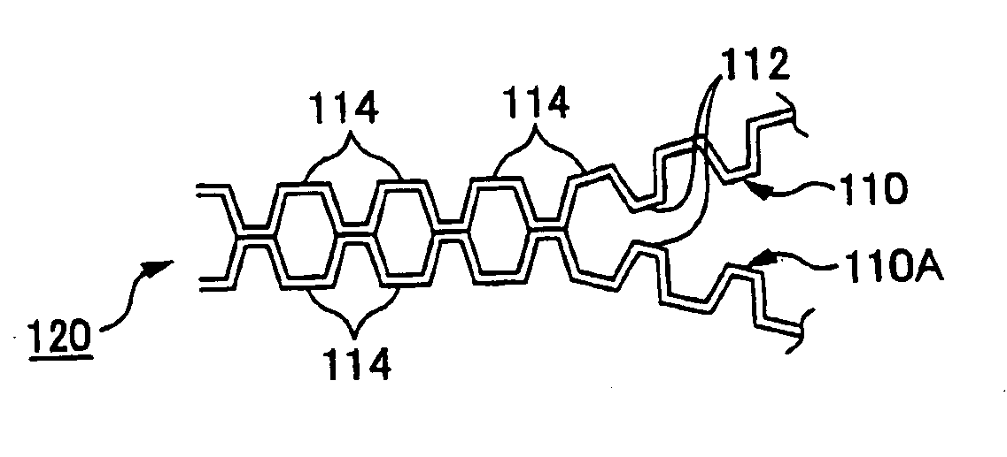
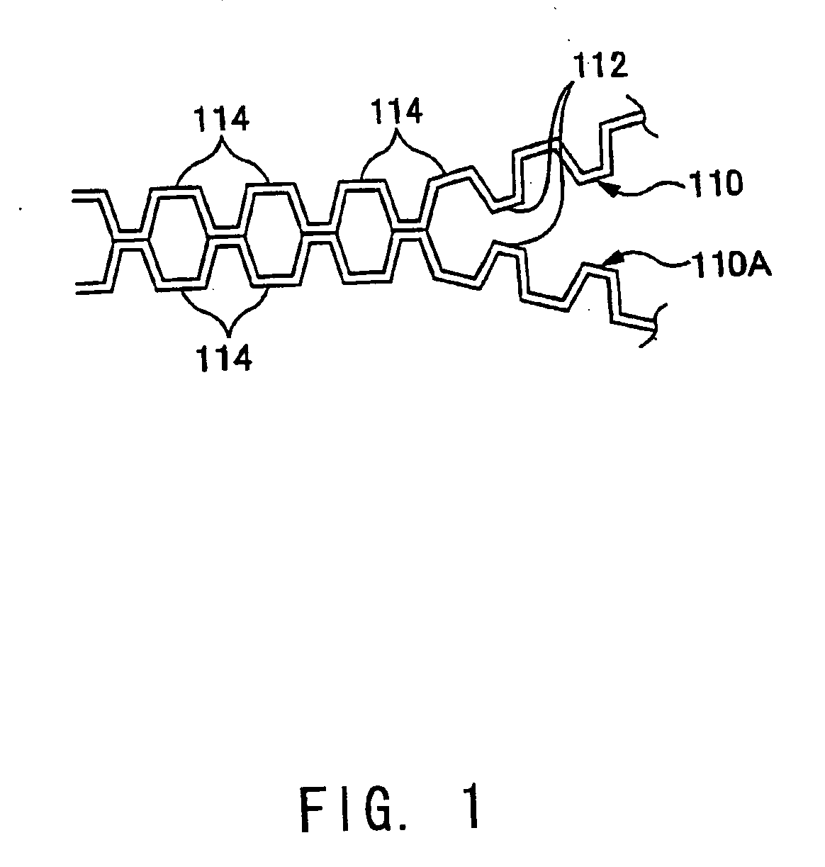
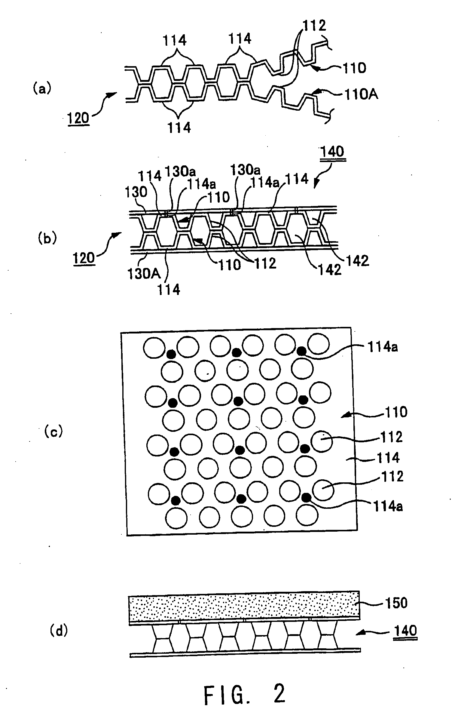
[0017] (2) A method for manufacturing a hollow structure plate according to the present invention comprises: introducing two thermoplastic resin sheets into a pressure-reduced chamber; attracting and attaching the resin sheets respectively to a circumferential surface of each of a pair of upper and lower emboss rollers that are arranged rotatably in the pressure-reduced chamber to form a multitude of hollow protrusions on each of the resin sheets in accordance with a shape of a pin projected in each of the emboss rollers; and thermally fusing the end faces of the hollow protrusions in a position of a contact line, i.e., a contact point, of the emboss rollers. Introduction guides are arranged respectively above and below a sheet-introducing opening portion of the pressure-reduced chamber, each of the introduction guides being inclined toward a direction of the contact line, i.e., the contact point, of each of the emboss rollers. Heating means for thermal fusion is provided between the introduction guides, the heating means being arranged in a non-contact manner between the resin sheets. Each of the resin sheets is attracted and attached respectively to the circumferential surface of each of the emboss rollers under a reduced pressure by maintaining opposing surfaces of the resin sheets in the pressure-reduced chamber at an atmospheric pressure and reducing a pressure at surfaces opposite therefrom.

Problems solved by technology

In this structure, when it is attempted to increase the height of a hollow protrusion to increase the thickness, the wall portion constituting the hollow protrusion turns into a film, so that the strength cannot be maintained.
If the thickness of the resin sheet is increased in order to solve this problem, then the weight is inevitably increased and the property of being lightweight is impaired.
However, the above-described manufacturing method has the following technical problems in terms of the shape or the properties, and cannot be adapted for manufacturing in practice.
First, often, the sheet cannot be attached onto the roller simply by evacuating the roller, and evacuation loss occurs, so that when forming hollow protrusions having a large height, molding is impossible.
Second, when the rollers are heated to a temperature at which the hollow protrusions of the resin sheets can be molded, the resin sheets get attached to the rollers, which makes mold release difficult.
On the other hand, if the molding temperature is too low, then the bottom surfaces of the hollow protrusions cannot be fused and joined together, even if they are in contact with each other.
Furthermore, when the difference in the size (diameter ratio) between the upper base and the lower base of each pin is small, not only does the mold-release property deteriorate, but also the following problem occurs: in the molded hollow structure plate, the amount of resin for the hollow protrusions is increased and the balance with the liner portion in which no hollow protrusion is formed collapses, so that webbing occurs and thus the formativeness deteriorates.
Furthermore, such a hollow structure plate has a poor sound absorbency, and it is necessary to attach a porous sheet-shaped member such as an urethane foam sheet, a non-woven fabric, and a woven fabric in order to improve the sound absorbency.
Furthermore, in a commonly used sound absorbing material, the sound absorbency depends greatly on the thickness thereof, so that for example, as the thickness of the porous sheet-shaped member becomes smaller, the sound absorbency, especially in the low or medium frequency region, becomes poorer.
Moreover, rock wool, plaster boards and the like that are used as interior materials for houses such as ceiling materials or wall materials are lightweight and have excellent sound absorbency and thermal insulation performance, but the rigidity and water resistance are poor.

Method used


Image

  • Hollow structure plate, manufacturing method thereof, manufacturing device thereof, and sound absorbing structure plate
  • Hollow structure plate, manufacturing method thereof, manufacturing device thereof, and sound absorbing structure plate
  • Hollow structure plate, manufacturing method thereof, manufacturing device thereof, and sound absorbing structure plate

Examples


example 1

[0063] A homopolypropylene sheet (melting point: 165° C., softening point: 120° C.) having a thickness of 0.5 mm and a Metsuke (weight per unit area) of 500 g / m2 in the melted state was placed on a vacuum molding plate having a length of 1000 mm and a width of 1000 mm in which hollow protrusions (emboss pins), whose height is 5.5 mm and whose diameter of the upper base is 2 mm and diameter of the lower base is 6 mm, were arranged in a staggered lattice arrangement with a pin interval of 2 mm, and vacuum molding was performed in off-line. The ends of the protrusions of the obtained two embossed sheets were thermally fused. Using this as a core member, homopolypropylene sheets having a thickness of 0.25 mm and a Metsuke of 250 g / m2 were attached as face material to the front and the back of this core member. Thus, a hollow structure plate having a total thickness of 11.5 mm and a Metsuke of 1500 g / m2 was obtained. Thereafter, a hole-opening process was performed to one of the liner po...

example 2

[0064] A hollow structure plate was obtained in the sane manner as in Example 1, and then a hole-opening process was performed to one of the liner portions of the hollow structure plate such that holes of φ2.5 mm were formed at an equal pitch at an opening ratio of 0.36%. The sound absorption coefficient of this perforated hollow structure plate was measured in a small reverberant chamber.

example 3

[0065] A hollow structure plate was obtained in the same manner as in Example 1, and then a hole-opening process was performed to one of the liner portions of the hollow structure plate such that holes of φ4.0 mm were formed at an equal pitch at an opening ratio of 0.36%. The sound absorption coefficient of this perforated hollow structure plate was measured in a small reverberant chamber.


PUM

PropertyMeasurementUnit
angleaaaaaaaaaa
diameteraaaaaaaaaa
diameteraaaaaaaaaa

Abstract

Introduction guides 12 are provided above and below a sheet-introduction opening portion of a pressure-reduced chamber 10, and heating means 17 is provided between the introduction guides. Each resin sheet 3 is attracted and attached respectively to the circumferential surface of a corresponding emboss roller 11 by reducing pressure. Pins 112 of the emboss roller 11 are truncated cone-shaped. The ratio of the total area of the lower bases of the pins 112 to the area of the circumferential surface of the emboss roller is 0.5 or more. The rising angle θ of the pin side face, in the vertical plane including the central axis of the pins 112, is in the range from 50 degrees to 70 degrees. Furthermore, a multilayered hollow structure plate 140 is formed by attaching non-air-permeable sheets 130 onto both the front and back of a core member obtained by fusing together hollow protrusions 112 in two thermoplastic resin sheets. A sound absorbing material 150 is provided on at least one of the front and back side thereof, and small holes 114a opened in the multilayered hollow structure plate are formed in liner portions 114 and the non-air permeable sheet 130 only in the positions that matches the liner portions 114.

Description

TECHNICAL FIELD [0001] The present invention relates to hollow structure plates, methods and apparatuses for manufacturing the same, and sound absorbing structure plates. BACKGROUND ART [0002] Plastic hollow structure plates, such as flute-shaped plastic cardboards (product name: Danplate manufactured by Ube-Nitto Kasei Co., Ltd.), corrugated plastic cardboards, plastic structure plates in which columnar independent air compartments are formed (product name: Plapearl manufactured by Kawakami Sangyo Co., Ltd.), are lightweight and have excellent water resistance, heat resistance, chemical resistance and other properties, and thus have conventionally been used in various applications such as building panels, containers, various boxes, and interior materials for, for example, houses, buildings, offices, and vehicles (e.g., see JP 2000-326430A as a honeycomb structure plate). [0003] Among these, hollow structure plates in which columnar independent air compartments (hereinafter, referre...

Claims


Application Information

Patent Timeline
Patent Type & Authority Applications(United States)
IPC IPC(8): B29C51/02B29C51/22B29C51/26B29C65/02B29C69/00B29D24/00B32B3/12B32B3/28E04B1/84E04C2/20E04C2/34G10K11/172
CPCB29C47/00Y10T428/24562B29C47/0033B29C47/0038B29C47/0054B29C51/02B29C51/225B29C51/24B29C51/261B29C51/267B29C65/02B29C65/028B29C66/0242B29C66/21B29C66/438B29C66/54B29C66/83513B29C2791/001B29C2791/006B29D24/008B29K2995/0002B29K2995/0067B29L2016/00B29L2024/00B29L2031/608B32B3/12B32B3/28B32B37/146B32B2607/00E04B1/86E04B2001/8428E04B2001/8433E04B2001/8471E04B2001/8476E04C2/20E04C2/3405E04C2002/3427E04C2002/3472G10K11/172B29C47/0019Y10T156/1712Y10T428/13Y10T428/24661Y10T156/1023B29C65/1432B29C47/0064B29C47/0066B29C47/065B29C66/53462B29C65/00B29C66/727B29C66/7252B29C65/08B29C66/73921B29C66/1122B29C66/1312B29C48/00B29C48/07B29C48/13B29C48/001B29C48/0017B29C48/0021B29C48/0022B29C48/21
Inventor NAKAJIMA, MASAHIKOMIYAZAKI, TAKESHIODA, TAKAYUKIKOZUKA, KENJI
Owner UBE NITTO KASEI CO LTD
Why Eureka
Try Eureka