
Acoustic backing material for small-element ultrasound transducer arrays

Inactive Publication Date: 2005-06-16
GENERAL ELECTRIC CO
View PDF2 Cites 35 Cited by
  • Summary
  • Abstract
  • Description
  • Claims
  • Application Information

AI Technical Summary

Benefits of technology

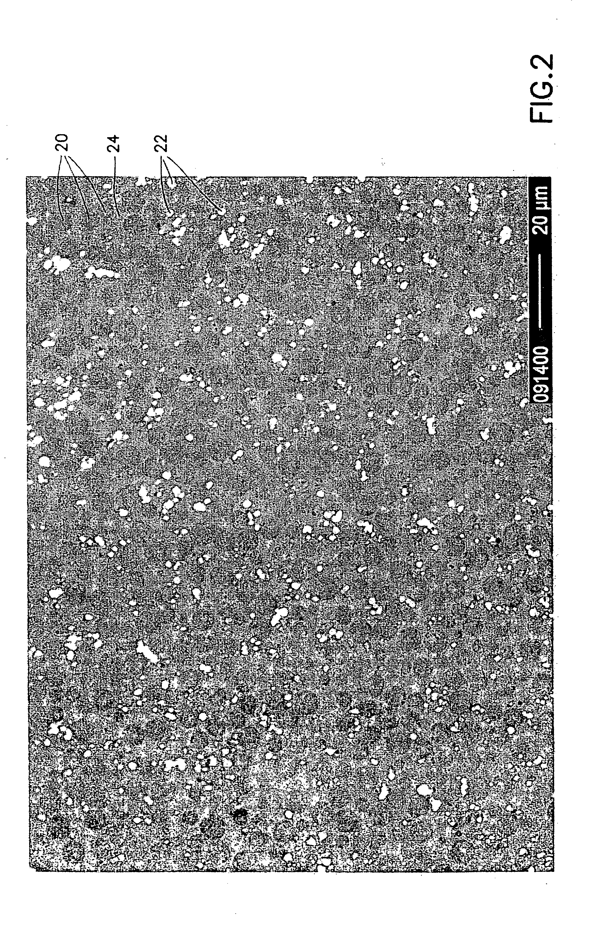
[0008] The present invention is directed to a fine-pitch acoustic transducer array that has a backing made of acoustically attenuative material prepared by homogeneously combining a matrix component and filler components having a particle size less than one-fifth (preferably less than one-tenth) of the smallest dimension of the elements making up the array. In accordance with certain embodiments of the invention, the acoustically attenuative material comprises 25-45 wt. % tungsten particles, 15-35 wt. % silicone particles and 40-60 wt. % epoxy.
[0009] It should be understood at the outset that the aspects of the invention disclosed herein are not limited to piezoelectric ceramic transducer elements, but rather apply to any array having fine-pitch ultrasound transducer elements. In particular, the elements in a two-dimensional transducer array may have a dimension (e.g., width or diameter) on the order of 300 microns or smaller. Other types of transducer elements that may be used in conjunction with the acoustic backing disclosed herein include micromachined ultrasound transducers of the capacitive (cMUTs) and piezoelectric (pMUTs) varieties.
[0010] One aspect of the invention is an ultrasonic transducer device comprising: an element that converts impinging acoustic energy into outputted electrical energy and that converts inputted electrical energy into outgoing acoustic energy, and a body of acoustically attenuative material that is acoustically coupled to the element, wherein the acoustically attenuative material comprises particles of an acoustic scattering material having an average diameter less than 20 microns and particles of an acoustic absorbing

Problems solved by technology

This prevents the acoustic energy from being reflected from structures or interfaces behind the transducer and back into the piezoelectric material, thereby reducing the quality of the acoustic image obtained from reflection within the patient.

Method used


Image

  • Acoustic backing material for small-element ultrasound transducer arrays
  • Acoustic backing material for small-element ultrasound transducer arrays
  • Acoustic backing material for small-element ultrasound transducer arrays

Examples


Embodiment Construction

[0017] For the purpose of illustration, various embodiments of the invention will be described that belong to the class of piezoelectric ceramic ultrasonic transducers. However, it should be understood that the aspects of the invention disclosed herein also have application in other types of fine-pitch ultrasound transducer arrays, such as cMUTs and pMUTs.

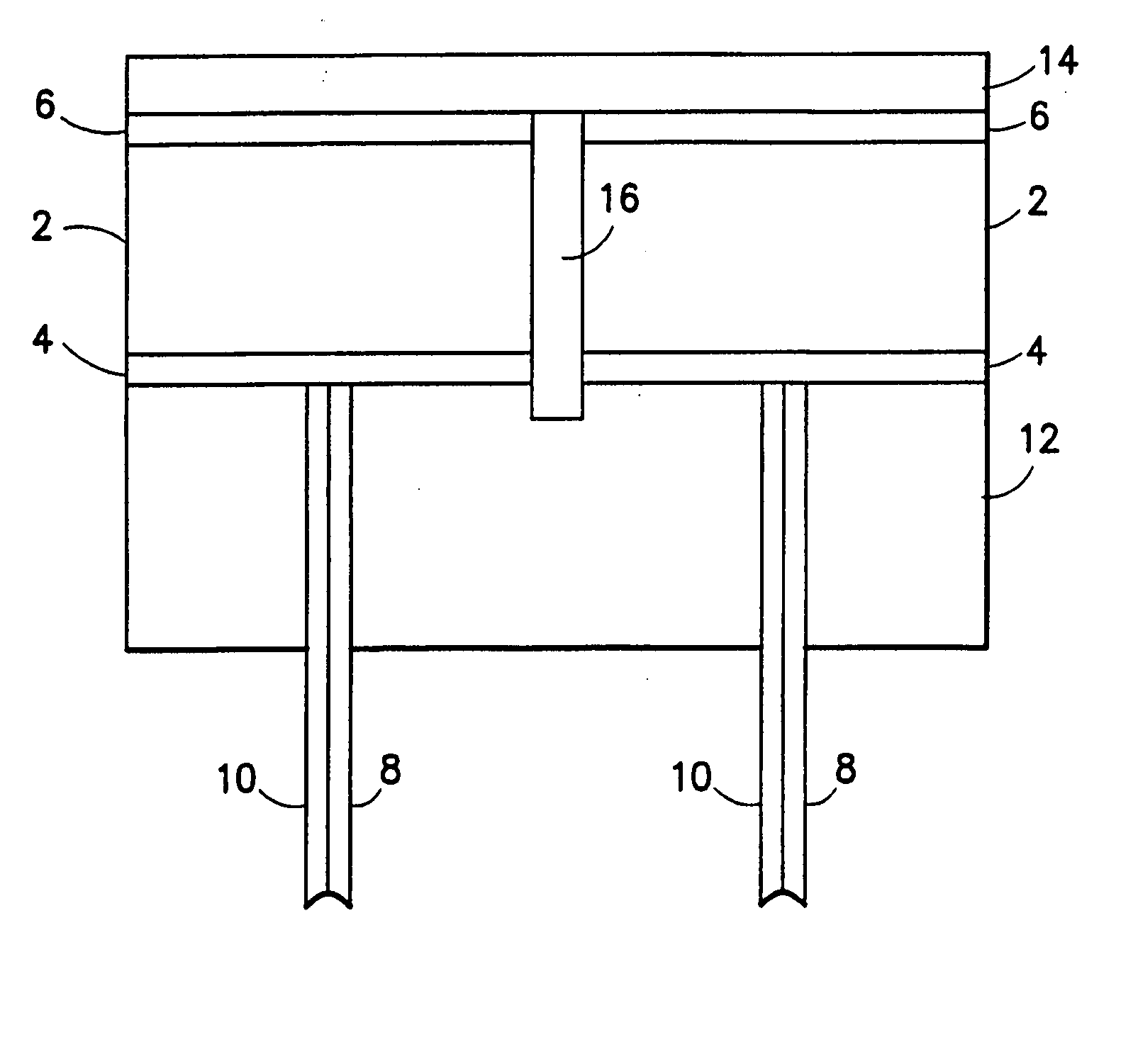
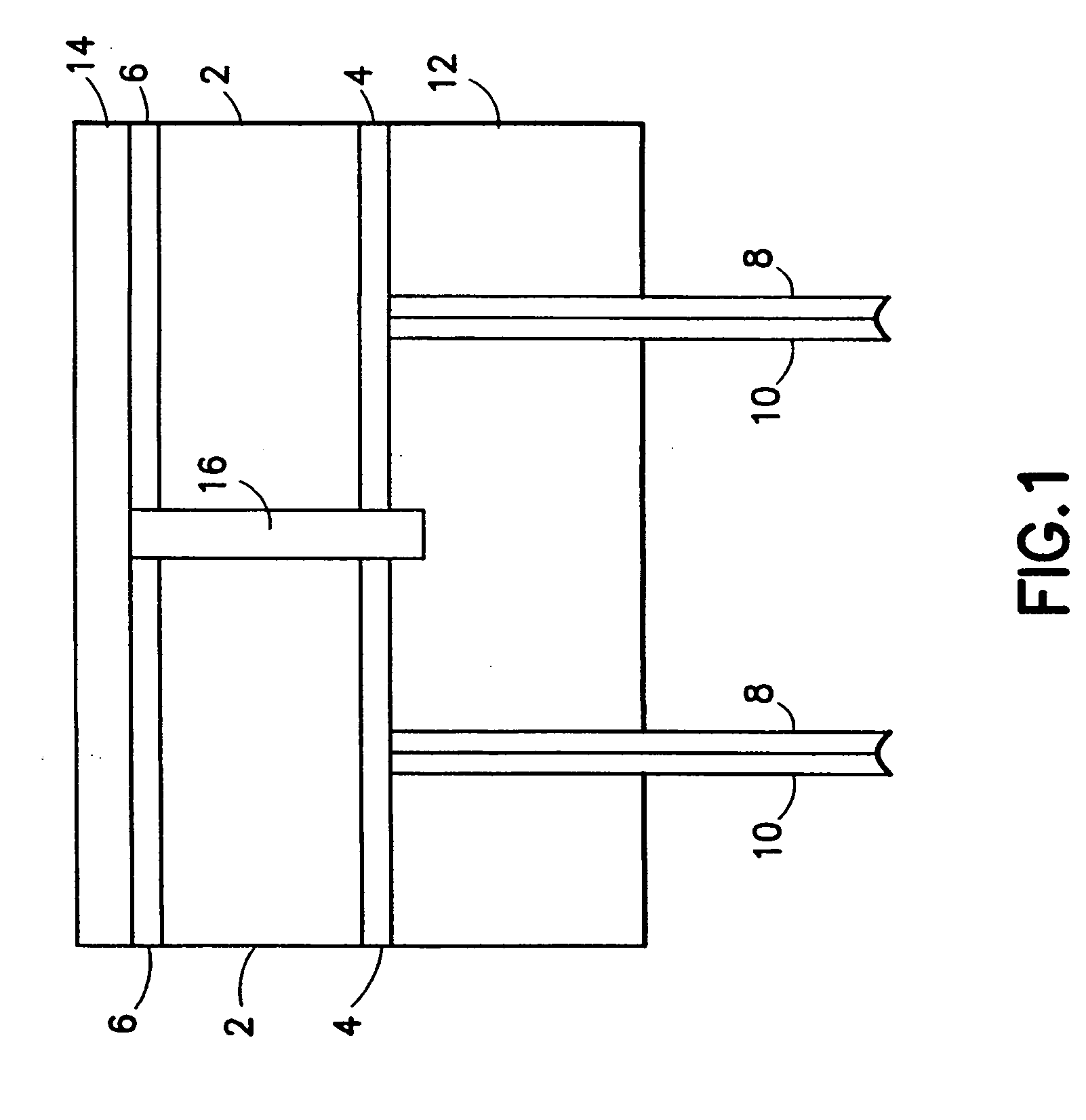
[0018]FIG. 1 shows an exemplary ultrasound transducer element comprising a piezoelectric ceramic layer 2 having a bottom surface that has been metallized to form a signal electrode 4 and a top surface that has been metallized to form a ground electrode 6. An acoustic impedance matching layer 14 made of electrically conductive material is joined to the metallized top surface of the ceramic by a thin (acoustically transparent) layer of epoxy (not shown) that allows ohmic contact between the matching layer 14 and the ground electrode 6. As partly depicted in FIG. 1, matching layer 14 is common to all transducer elements, meaning that...


PUM


Abstract

A fine-pitch acoustic transducer array that has a backing made of acoustically attenuative material. The backing material is prepared by homogeneously combining a matrix component and filler components having an average particle size less than one-fifth (preferably less than one-tenth) of the smallest dimension of the elements making up the array. In certain embodiments, the acoustically attenuative material comprises 25-45 wt. % tungsten particles, 15-35 wt. % silicone particles and 40-60 wt. % epoxy.

Description

BACKGROUND OF THE INVENTION [0001] This invention generally relates to ultrasound transducer arrays. In particular, the invention relates to ultrasound transducer arrays comprising small elements, such as small-element arrays used in ultrasound imaging. [0002] Conventional ultrasound imaging transducers generate acoustic energy via a piezoelectric effect in which electrical energy is converted into acoustic energy using a poled piezoelectric ceramic material. The acoustic energy that is transmitted in the forward direction, which is in the direction of the patient being scanned, is coupled to the patient through one or more acoustic matching layers. However, the acoustic energy transmitted in the direction away from the patient being scanned is typically absorbed in and / or scattered by an acoustic backing material (also referred to herein as “acoustically attenuative material”) located on the backside of the transducer array. This prevents the acoustic energy from being reflected fr...

Claims


Application Information

Patent Timeline
IPC IPC(8): B06B1/02A61B8/00G10K11/00G10K11/165H01L41/08
CPCG10K11/002
Inventor BAUMGARTNER, CHARLES E.MILLS, DAVID M.
Owner GENERAL ELECTRIC CO
Learn More