Battery pack

a battery pack and battery technology, applied in the field of batteries, can solve the problems of battery entering a dangerous state, risk of overcharge, abnormal heat generation, etc., and achieve the effect of reducing costs and improving efficiency

Inactive Publication Date: 2005-06-16
SONY CORP
View PDF6 Cites 61 Cited by
  • Summary
  • Abstract
  • Description
  • Claims
  • Application Information

AI Technical Summary

Benefits of technology

[0018] According to the invention, by using a DC / DC converter as a charging voltage converter for controlling the voltage of the primary battery, the efficiency can be improved and the miniaturization and the reduction in costs can be realized as compared with the case of using the regulator.
[0019] According to the invention, by providing the switch for switching the charging power sources, the state where a current flows reversely from the charger side to the primary battery when the primary battery is attached can be prevented and the state where the current from the charger and the current from the primary battery side flow simultaneously can be prevented.

Problems solved by technology

When the battery enters such an overcharge state, a possibility that the battery enters a dangerous state occurs.
However, there is a risk of occurrence of the overcharge due to a failure of a charger or use of a charger for a different kind of battery.
When (+) and (−) terminals of the battery are short-circuited, a large current flows, so that there is a risk of abnormal heat generation.
Therefore, when a residual capacity of the battery is extinguished at a place where the user has gone to, there is such inconvenience that portable electronic apparatuses such as cellular phone, PDA (Personal Digital Assistants), digital camera, camcoder (a general abbreviated name of “camera and recorder”, video camera+recorder) , and the like cannot be used.
However, there is such a problem that the user has to separately carry a charging pack.
If the voltage is controlled by the regulator, efficiency is low and a large electric power is wastefully consumed.
Further, since the regulator is not small, a circuit cannot be miniaturized by the method of controlling by the regulator,

Method used


Image

  • Battery pack
  • Battery pack
  • Battery pack

Examples


first embodiment

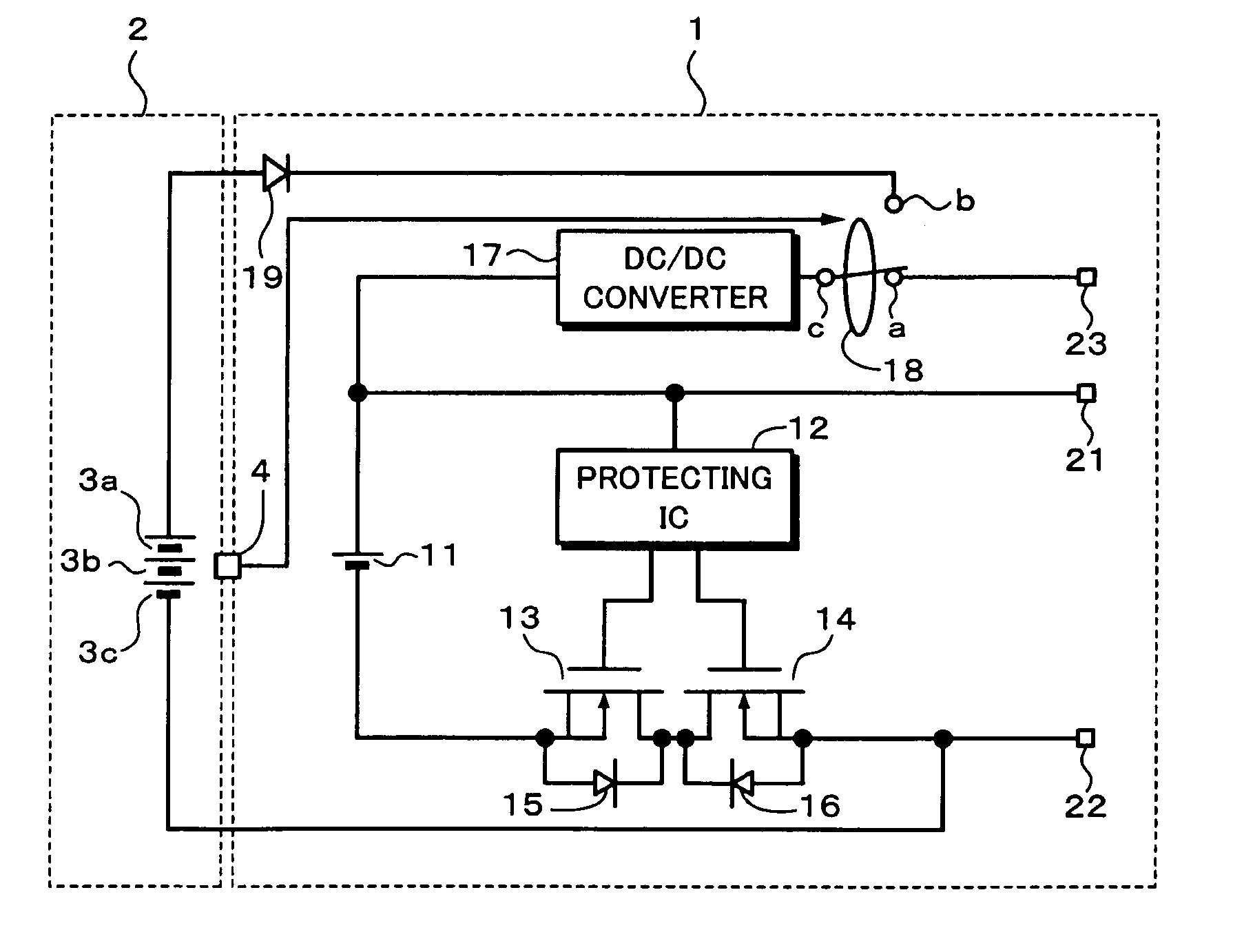
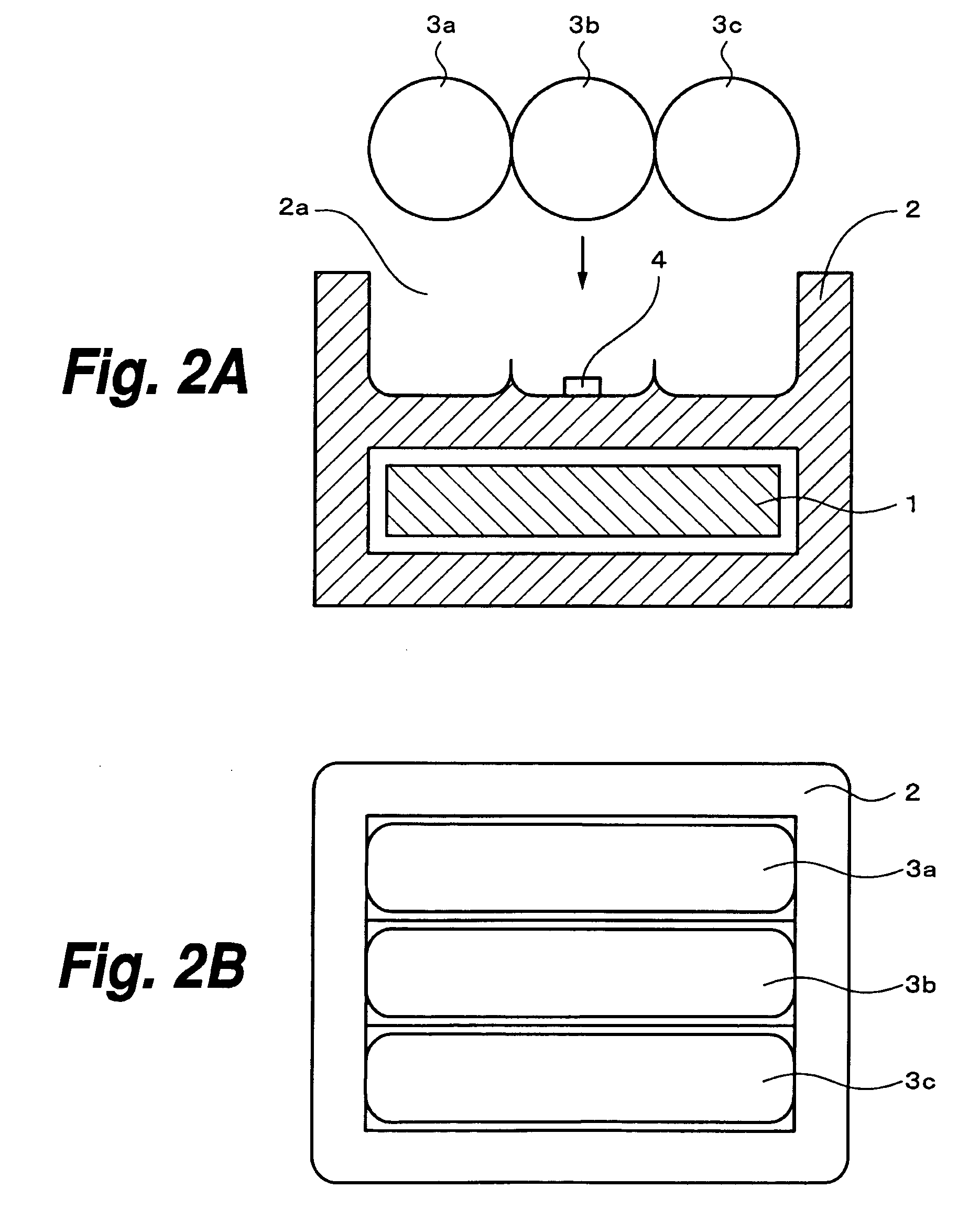
[0031] the invention will be described hereinbelow with reference to FIG. 1. In FIG. 1, reference numeral 1 denotes a battery pack of a secondary battery and 2 indicates a primary battery holder. A detecting switch 4 which is turned on / off in accordance with whether or not primary batteries, for example, three primary batteries 3a, 3b, and 3c have been attached to the primary battery holder 2 is provided. Each of the primary batteries 3a to 3c is an AA size (R6) battery.

[0032] A construction using the three primary batteries is shown as an example and one or more primary batteries can be used. As each of the primary batteries 3a to 3c, a manganese battery, an alkaline battery, a lithium battery, an air battery, or the like can be used. In each of FIG. 1 and other connection diagrams, only a connecting construction in the state where the primary batteries 3a to 3c are attached is shown for simplicity of explanation.

[0033]FIGS. 2A, 2B, 3A, and 3B show constructions of one and another...

second embodiment

[0053]FIG. 4 shows a circuit construction of the invention. Portions corresponding to those in the construction of FIG. 1 are designated by the same reference numerals. A voltage monitor 24 is provided as control means, the voltage values of the primary batteries 3a to 3c are detected by the voltage monitor 24, and the charge change-over switch 18 is controlled in accordance with a detection result.

[0054] In the normal state, an output detection signal of the voltage monitor 24 is equal to “0” and the charge change-over switch 18 selects the input terminal (a) to which the output of the external charger is supplied. When the primary batteries 3a to 3c are attached and the voltage values of the primary batteries 3a to 3c detected by the voltage monitor 24 are equal to the set voltage value or more, the output detection signal of the voltage monitor 24 is set to “1”. The charge change-over switch 18 is automatically switched from the charger side (input terminal (a)) to the primary ba...

third embodiment

[0055]FIG. 5 shows a circuit construction of the invention. Portions corresponding to those in the construction of FIG. 1 are designated by the same reference numerals. A voltage monitor 25 is provided as control means, the voltage value of the charging terminal 23 is detected by the voltage monitor 25, and the charge change-over switch 18 is controlled in accordance with a detection result.

[0056] In the normal state, a detection signal of the voltage monitor 25 is equal to “1” and the charge change-over switch 18 selects the input terminal (b) to which the outputs of the primary batteries 3a to 3c are supplied. When the external charger is attached and the voltage value of the charging terminal 23 detected by the voltage monitor 25 is equal to the set voltage value or more, the detection signal of the voltage monitor 25 is set to “0”. The charge change-over switch 18 is automatically switched from the primary battery side (input terminal (b)) to the charger side (input terminal (a)...


PUM

PropertyMeasurementUnit
charge control voltageaaaaaaaaaa
voltageaaaaaaaaaa
voltageaaaaaaaaaa

Abstract

A detecting switch which is turned on/off in accordance with whether or not primary batteries have been attached to a primary battery holder is provided. In a normal state where no primary battery is attached, terminals (a, c) of a charge change-over switch are connected by a detection signal of the detecting switch, so that a voltage supplied from an external charger is inputted to a DC/DC converter. A secondary battery is charged by a predetermined value output of the DC/DC converter. When the primary batteries are attached, the detecting switch is turned on and terminals (b, c) of the charge change-over switch are connected, so that an output voltage of the primary batteries is inputted to the DC/DC converter. The secondary battery is charged by the predetermined value output of the DC/DC converter. Even when there is no charger, the secondary battery can be charged by the primary batteries and charging power sources are automatically switched.

Description

BACKGROUND OF THE INVENTION [0001] 1. Field of the Invention [0002] The invention relates to a battery pack which has both a primary battery and a secondary battery such as a lithium ion battery or the like and which enables the secondary battery to be charged by the primary battery. [0003] 2. Description of the Related Arts [0004] Secondary batteries are widely used in portable electronic apparatuses. Since a lithium ion battery is weak against an overcharge or an overdischarge, in general, it has a construction of a battery pack in which a battery cell and a protecting circuit are integrated. The protecting circuit has three functions of protection against the overcharge, the overdischarge, and an overcurrent. Those protecting functions will be simply explained hereinbelow. [0005] The overcharge protecting function will now be described. When the lithium ion battery is charged, a battery voltage continues to rise even after exceeding a full charge state. When the battery enters su...

Claims


Application Information

Patent Timeline
Patent Type & Authority Applications(United States)
IPC IPC(8): G01R31/36H01M2/10H01M6/50H01M10/42H01M10/44H01M10/46H02J7/00H02J7/34
CPCH01M6/5033H01M10/42H01M10/46H02J7/0031H02J2007/004H02J7/0055H02J2007/0037H02J2007/0039H02J7/0054H02J7/00302H02J7/00304H02J7/00306H02J7/342H02J2207/40Y02E60/10
Inventor ORIKASA, HIRONOBU
Owner SONY CORP
Why Eureka
Try Eureka