Radar detection device employing a scanning antenna system

a detection device and scanning antenna technology, applied in the field of microwave radar systems, can solve the problems that the homoodyne radar cannot effectively determine if the detected movement is detected, and the need for a solution in the industry has not yet been addressed, and achieve the effect of suppressing hand motion

Inactive Publication Date: 2005-06-16
GEORGIA TECH RES CORP
View PDF24 Cites 125 Cited by
  • Summary
  • Abstract
  • Description
  • Claims
  • Application Information

AI Technical Summary

Benefits of technology

[0006] The present invention provides systems and methods for detecting a respiration signal in a target area while rejecting hand motion clutter. Briefly described, in architecture, one embodiment of the system, among others, can be implemented as follows. The system includes a scanning antenna configured to scan a transmitted continuous wave (CW) microwave signal azimuthally across a horizontal line in the target area. Also, the system includes a control system that tracks the position of the scanning antenna along the horizontal line. A signal processing system then suppresses the hand motion while preserving the respiration signal from a living subject in the target area. The amplitude of the reflected microwave signals from the target area and the positional data of the living subject are displayed to the operator after the cancellation of the self-generated motion clutter.

Problems solved by technology

Thus, when hand motion is present, the homodyne radar cannot effectively determine if the detected movement signature is from the subject or from the stationary wall.
Thus, a heretofore unaddressed need exists in the industry to address the aforementioned deficiencies and inadequacies.

Method used


Image

  • Radar detection device employing a scanning antenna system
  • Radar detection device employing a scanning antenna system
  • Radar detection device employing a scanning antenna system

Examples


Embodiment Construction

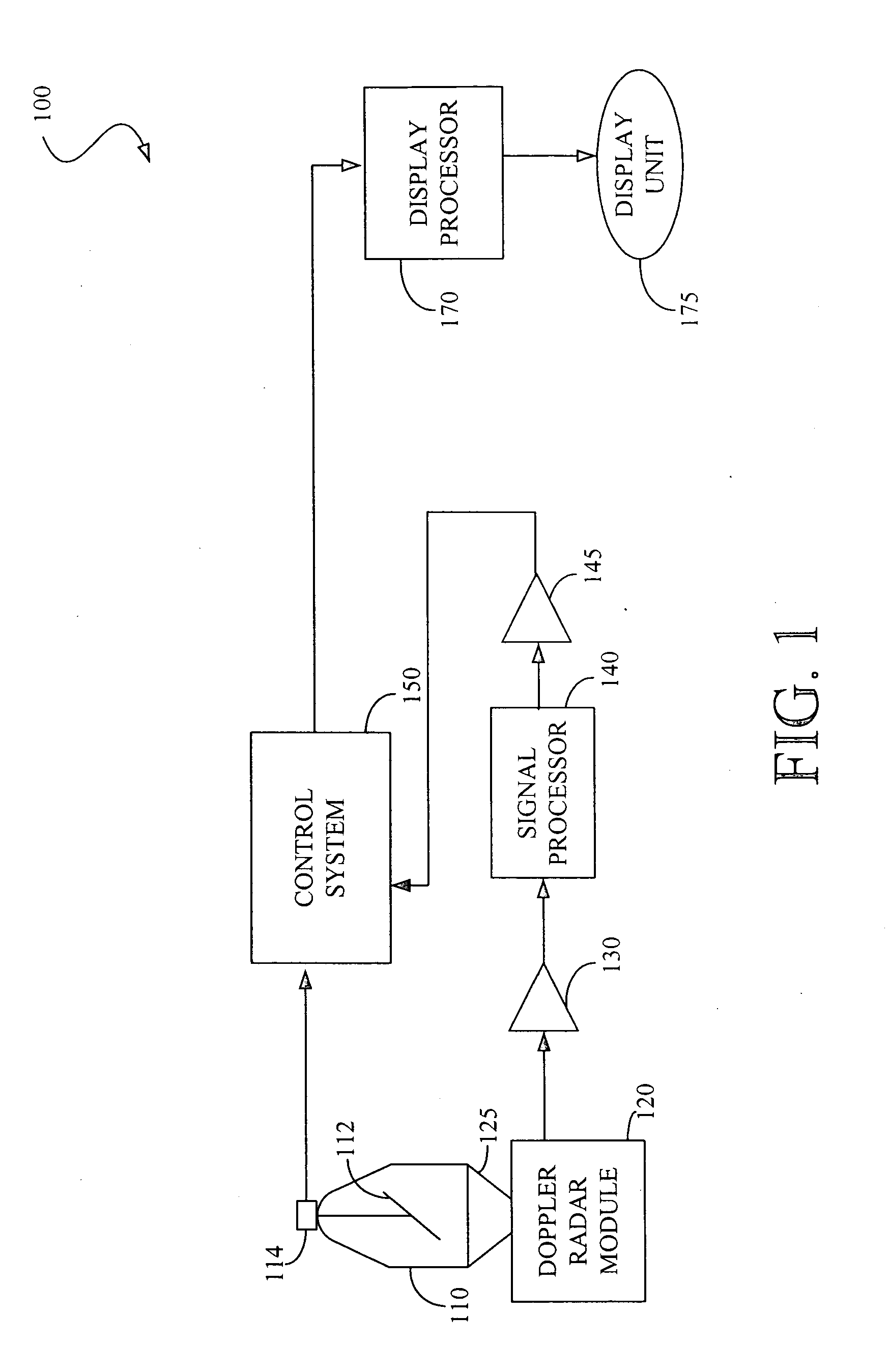
[0026]FIG. 1 shows a diagram of a possible embodiment of a radar detection device 100 employing one embodiment of the radar scanning system (“scanner”) 10. In this example, the radar detection device 100 comprises a homodyne Doppler radar module 120 that generates a microwave continuous wave (CW) signal at 10.525 GHz. However, other devices 100, systems 110, and microwave frequencies may also be used.

[0027] The CW signal is generated using a solid state Gunn device transmitter (not shown). The resulting CW signal is transmitted through a vertical pointing antenna 125. A mechanical scanner 110 is positioned on top of the vertical antenna 125 to make a scanning antenna assembly. Accordingly, a rotating 45-degree mirror 112 inside the mechanical scanner 110 redirects a transmitting microwave beam from the vertical pointing antenna 125 along an azimuthal horizontal axis 90 degrees from the vertical.

[0028] The CW microwave homodyne radar operating at 10.525 GHz supplies approximately 3...


PUM


Abstract

Systems and methods for detecting a respiration signal in a target area are disclosed. Briefly described, in architecture, one embodiment of the system, among others, can be implemented as follows. The system includes a scanning antenna configured to transmit a microwave signal across a horizontal axis in the target area. Also, the system includes a control system that tracks the position of the scanning antenna along the horizontal axis. A signal processing system then detects a respiration signal of a living subject in the target area from reflected microwave signals from the target area and the positional data. Other systems and methods are also provided.

Description

TECHNICAL FIELD [0001] The present invention is generally related to microwave radar systems and, more particularly, is related to systems and methods for detecting a respiration signal, through a non-conducting intervening wall with a microwave radar system. BACKGROUND OF THE INVENTION [0002] One recent use of homodyne radar system involves the detection of minute body movements that are associated with human respiratory activity. This approach is based on the principle that breathing produces measurable phase changes in electromagnetic waves as they reflect off of the skin surface of the moving thorax of a living person. When the target surface is moving, as does the surface of the chest in conjunction with respiratory and cardiac activities, corresponding variations will be observed in the difference of the phase between the received and transmitted signal. The observed variations can be used to determine motion-related target parameters such as displacement and velocity. [0003] ...

Claims


Application Information

Patent Timeline
Patent Type & Authority Applications(United States)
IPC IPC(8): G01S13/56G01S13/89
CPCA61B5/0507G01S13/89G01S13/888G01S13/56
Inventor GRENEKER, EUGENE F. IIIASBELL, OSCAR DAVIDGEISHEIMER, JONATHAN L.
Owner GEORGIA TECH RES CORP
Why Eureka
Try Eureka