Shooting lens having vibration reducing function and camera system for same

a technology of vibration reduction and shooting lens, which is applied in the field of shooting lens, can solve the problems of vibration decreasing, vibration decreasing, and gradual drift of the vibration reduction mechanism, and achieve the effects of accurate correction, correcting properly and stably, and robustness of the reference signal against an external disturban

Inactive Publication Date: 2005-06-16
NIKON CORP
View PDF6 Cites 40 Cited by
  • Summary
  • Abstract
  • Description
  • Claims
  • Application Information

AI Technical Summary

Benefits of technology

[0132]FIG. 5A, FIG. 5B, and FIG. 5C are schematic diagrams showing a simulation result of a vibration reduction operation according to the first embodiment.
[0133] When a motion vector is fed back to a reference signal shown in FIG. 5A, the reference signal accurately contains a DC offset and a drift output of the angular speed sensor 10. Specially, unlike with the conventional moving average method, a phase delay of the drift output can be accurately corrected.
[0134] In particular, a reference signal is a low frequency signal; therefore, it can be properly and stably corrected even by a motion signal with a long sampling interval. Even if a reference signal varies due to an external disturbance, feeding back a motion vector to the reference signal enables the reference value to be restored to a normal value. Thus, the robustness of a reference signal against an external disturbance is very high.
[0135] As a result, an error in a reference signal shown in FIG. 5B (an error in actual real angular speed data) is smaller than an error in a simulation result of a related art reference shown in FIG. 5B. The accuracy of a reference signal is improved so that a high vibration reduction effect as shown in FIG. 5C is obtainable. In addition, owing to a long update interval of the motion vector, the load of the system to calculate the motion vector is very low.
[0136]FIG. 6 illustrates a criterion of a vibration reduction performance according to the first embodiment. In the prior art (curves B and C shown in FIG. 6), the optical vibration reduction system 100 drifts as time elapses so that it is difficult to reduce the image vibration amount. In contrast, according to the first embodiment (curves D and E shown in FIG. 6), the drifting amount of the optical vibration reduction system 100 is small, so that it is able to reduce the image vibration amount during the exposure.
[0137] In the first embodiment, lead compensation may be made on the phase of a motion vector at step S21 shown in FIG. 7. For example, the phase-compensated motion vector Vnow′ is obtainable according to the following formula:

Problems solved by technology

In the known vibration reduction control technique, a DC offset and a drift contained in an output of an angular speed sensor cause problems, because odd components such as these DC offset and drift have to be removed in order to accurately detect the vibration of a subject image.
However, these odd components vary depending on the temperature and use conditions of the angular speed sensor.
Thus, the values of the DC offset and drift measured for shipment are not usable for actual shooting.
However, by this known technique, a reference signal has various errors. FIG. 12A, FIG. 12B, and FIG. 12C show a simulation result of a conventional reference signal estimation.
Although a high frequency component of a hand vibration decreases, the vibration reduction mechanism gradually drifts over time.
If these techniques are applied to electronic still cameras, the following problems [1] and [2] will arise.
Feeding back the motion signal with a long interval to the target drive position cannot achieve sufficient vibration reduction effect.
Thus, it is difficult to estimate accurate extrapolation so that discontinuous errors may occur in the extrapolation.
The errors in the extrapolation results in errors in the control of the target drive position.
As a result, the vibration reduction effect may conspicuously deteriorate.
The high-pass filter does not allow low frequency components corresponding to the drift and offset to pass therethrough.
Consequently, the technique disclosed in the References 1 and 2 is not able to properly correct the drift and offset of low frequency range.
Because of this, the technique disclosed in the References 1 and 2 cannot prevent the image vibration caused by a long-exposure shooting.
A strong bias power causes deterioration in the stability of the vibration reduction control; accordingly, it may cause the vibration reduction mechanism to oscillate at worst.
In addition, the inventors of the present invention have found that the feedback of the motion signal to the vibration reduction mechanism causes a problem that the vibration reduction mechanism is likely to oscillate because the stability of the vibration reduction control remarkably deteriorates by a synergistic effect of the feedback of the motion signal and the center bias.
The inventors have also found that the feedback of the motion signal to the vibration reduction control causes another problem that the vibration reduction mechanism moves unnecessarily when it stops.
When the output varies, it becomes difficult and inaccurate to estimate the reference signal of the angular speed sensor.
As a result, the reference signal contains a large error.
Accordingly, the vibration reduction would become inaccurate.
When the panning is preformed for a long time, the vibration reduction system would exceed its drive limit.

Method used


Image

  • Shooting lens having vibration reducing function and camera system for same
  • Shooting lens having vibration reducing function and camera system for same
  • Shooting lens having vibration reducing function and camera system for same

Examples


first embodiment

Description of Structure of First Embodiment

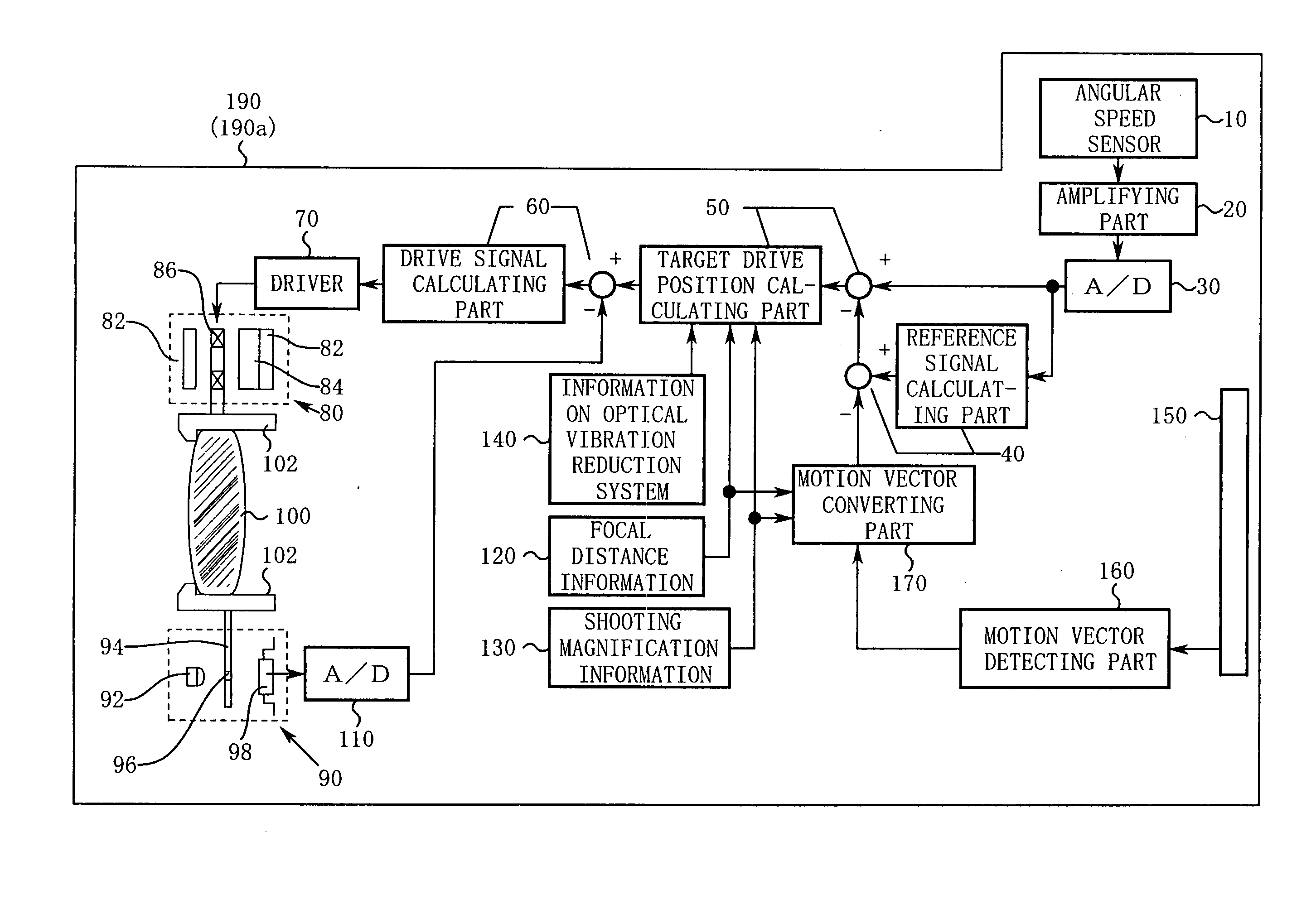
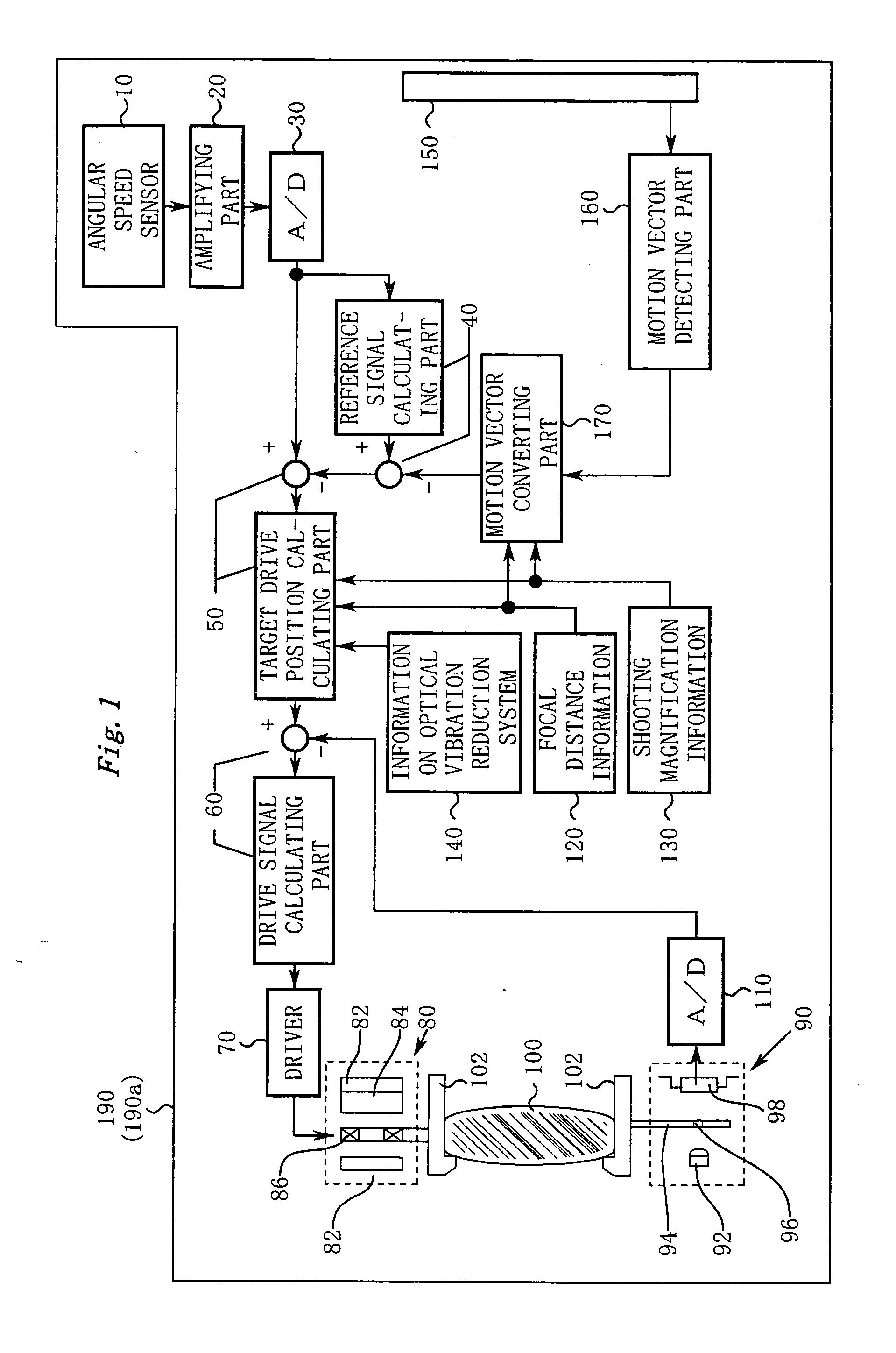
[0093]FIG. 1 shows a schematic block diagram of a camera system 190 (including a shooting lens 190a) according to the first embodiment of the present invention. In reality, the camera system 190 reduces a vibration of an image in two axis directions, horizontal and vertical directions. However, for simplicity, in FIG. 1, a vibration reduction mechanism for one axis is shown.

[0094] Next, the structure of each part shown in FIG. 1 will be described.

[0095] An angular speed sensor 10 detects a vibration of the camera system 190 as an angular speed using Coriolis force. An amplifying part 20 amplifies an output of the angular speed sensor 10. In addition, a low-pass filter may be disposed to reduce a high frequency noise in the sensor output. An A / D converting part 30 converts an output of the amplifying part 20 into digital angular speed data.

[0096] A reference signal calculating part 40 extracts a low frequency component from the angular ...

second embodiment

Description of Structure of Second Embodiment

[0140]FIG. 8 is a schematic diagram showing a camera system 290 (including a shooting lens 290a) according to a second embodiment of the present invention. FIG. 9 is a block diagram showing a principal structure of a vibration reduction control system.

[0141] Next, with reference to FIG. 8 and FIG. 9, the structure of each part of the camera system 290 will be described. For simplicity, description of structural parts that are in common with the first embodiment (FIG. 1) will be omitted.

[0142] First of all, a target drive position calculating part 50 (in detail, a part denoted by reference numeral 50a in FIG. 8) subtracts a reference signal from angular speed data so as to obtain an actual angular speed as a cause of a vibration of an image.

[0143] The target drive position calculating part 50 (in detail, a part denoted by reference numeral 50b in FIG. 8) converts the actual angular speed into a scale of the moving amount of a optical v...

third embodiment

Description of Structure of Third Embodiment

[0201]FIG. 13 is a schematic diagram showing a camera system (including a shooting lens 390a).

[0202] Next, with reference to FIG. 13, the structure of each part of the camera system 390 will be described. For simplicity, description of structural parts that are in common with the first embodiment (FIG. 1) will be omitted.

[0203] The third embodiment features a structure of which a gain changing part 200′ is disposed. The gain changing part 200′ adjusts the gain of a motion vector.

[0204] Connected to the gain changing part 200′ is a release button 201, a focus detecting part 202 that determines whether or not a subject is focused, and a panning detecting part 203 that determines whether or not the camera is panning.

Relation Between the Claims and the Third Embodiment

[0205] Next, the relation between the terminology used in claims and the terminology used in the third embodiment will be described. It should be noted that the relation re...


PUM


Abstract

The invention includes a vibration reduction mechanism, a vibration detecting part, a reference signal generating part, a target drive position calculating part, and a driving part. The vibration reduction mechanism reduces a vibration of a subject image. The vibration detecting part outputs a vibration detection signal. The reference signal generating part estimates a reference signal of the vibration detection part. The target drive position calculating part obtains a vibration component from a difference between the vibration detection signal and the estimated reference signal to obtain a target position to which the vibration reduction mechanism is driven. The driving part controls the vibration reduction mechanism to follow the target position. Particularly, the reference signal generating part corrects the reference signal according to a motion signal obtained from a captured image. An accurate reference signal can be obtained by the correction, thereby improving the performance of the vibration reduction.

Description

CROSS REFERENCE TO RELATED APPLICATION [0001] This application is a Continuation-in-Part of U.S. patent application Ser. No. 10 / 893,501, filed on Jul. 19, 2004, and claims the benefit of priority from Japanese Application Nos. 2003-279688 and 2003-280097, both filed Jul. 25, 2003. The disclosure of the prior application is hereby incorporated by reference herein in its entirety.BACKGROUND OF THE INVENTION [0002] 1. Field of the Invention [0003] The present invention relates to a shooting lens for reducing a vibration of an image of a subject and a camera system therefor. [0004] 2. Description of the Related Art [0005] There has been a known technique for driving a vibration reduction mechanism to reduce a vibration of an image of a subject due to a hand vibration or the like. Such a known technique includes a vibration reduction mechanism (such as an optical vibration reduction system or the like) and an angular speed sensor. The angular speed sensor detects vibration of a shooting ...

Claims


Application Information

Patent Timeline
Patent Type & Authority Applications(United States)
IPC IPC(8): H04N5/232
CPCH04N5/23248H04N5/23287H04N5/23258H04N5/23254H04N23/6811H04N23/68H04N23/6812H04N23/687
Inventor TOMITA, HIROYUKIUSUI, KAZUTOSHIMATSUMOTO, TSUYOSHI
Owner NIKON CORP
Why Eureka
Try Eureka