Optical detector for a particle sorting system

a particle sorting and optical detector technology, applied in the direction of optical radiation measurement, fluorescence/phosphorescence, instruments, etc., can solve the problems of inability to detect light signals of short duration, prior optical detection systems are at times inaccurate and poor, and conventional detection systems have significant drawbacks, etc., to achieve cost-effective, efficient and accurate monitoring

Active Publication Date: 2005-06-16
CYTONOMEST
View PDF21 Cites 80 Cited by
  • Summary
  • Abstract
  • Description
  • Claims
  • Application Information

AI Technical Summary

Benefits of technology

[0008] The optical system cost effectively and simultaneously captures extinction signals, one or more optical scatter signals, and one or more fluorescence signals all at low light levels ...

Problems solved by technology

Conventional detection systems have significant drawbacks.
For example, prior optical detection systems are at times inaccurate and provide poor results due to the difficulty of observing low light level signals from fluorescent labels on particles when spread out over a large area.
Prior optical systems ...

Method used


Image

  • Optical detector for a particle sorting system
  • Optical detector for a particle sorting system
  • Optical detector for a particle sorting system

Examples


Embodiment Construction

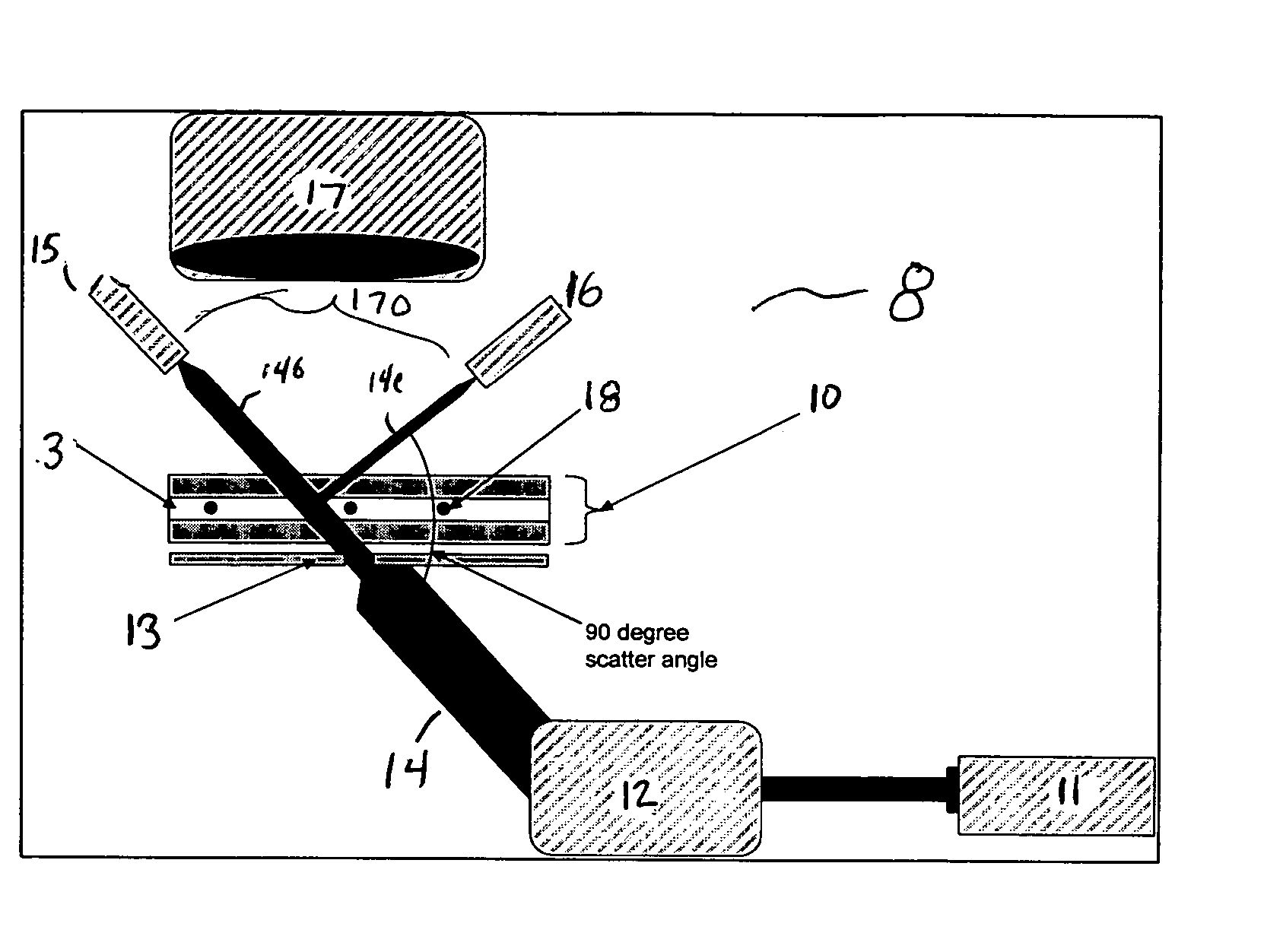
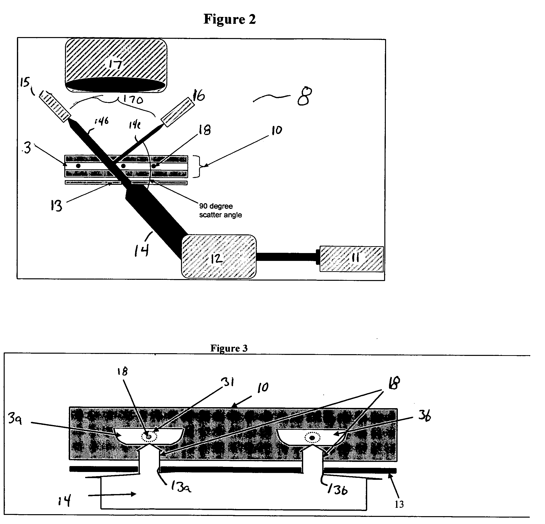
[0021] The present invention provides an optical system for monitoring and detecting particle flow through an array of channels. The present invention will be described below relative to illustrative embodiments. Those skilled in the art will appreciate that the present invention may be implemented in a number of different applications and embodiments and is not specifically limited in its application to the particular embodiments depicted herein.

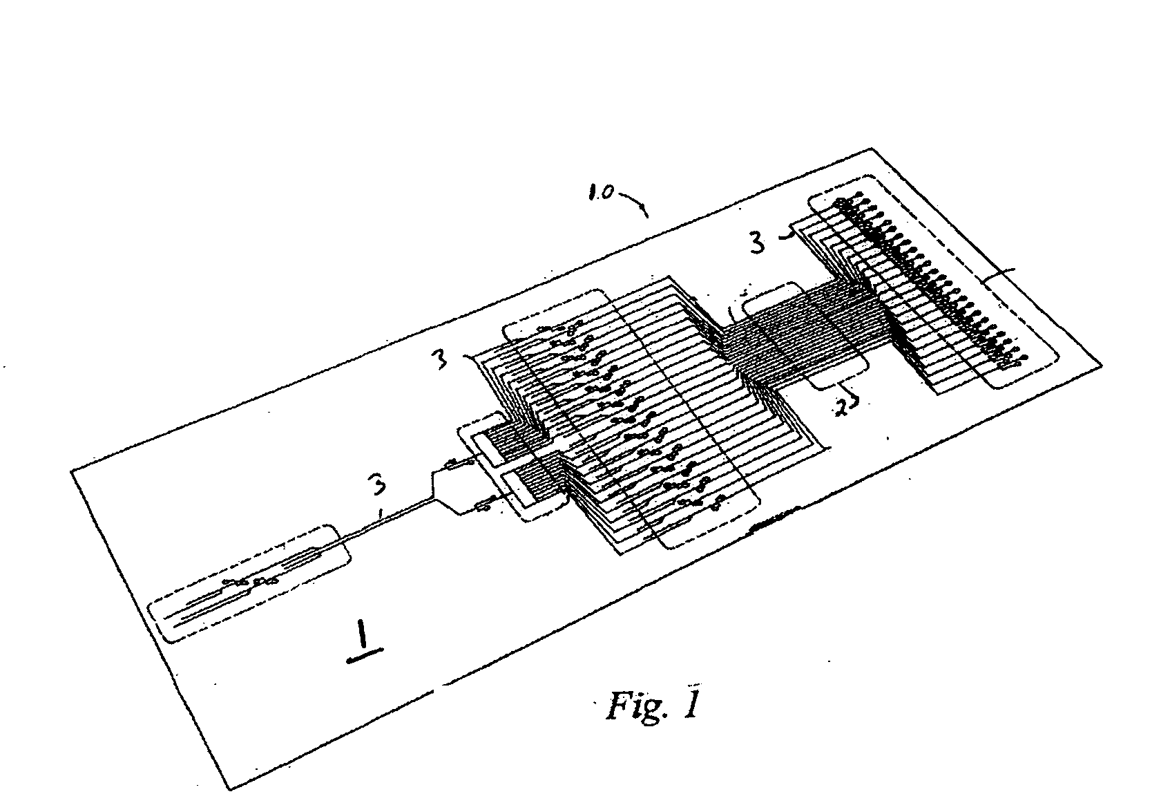
[0022]FIG. 1 illustrates a microfluidic system 10 suitable for implementing an illustrative embodiment of the invention, including a plurality of channels for conveying a substance, such as particles or cells, therethrough. The illustrative microfluidic system 10 comprises a substrate 1 having a plurality of channels, such as microchannels 3, disposed therein. The channels transport fluid and / or particles through the microfluidic system 10 for processing, handling, and / or performing any suitable operation on a liquid sample. As used herein...


PUM


Abstract

An optical system for acquiring fast spectra from spatially channel arrays includes a light source for producing a light beam that passes through the microfluidic chip or the channel to be monitored, one or more lenses or optical fibers for capturing the light from the light source after interaction with the particles or chemicals in the microfluidic channels, and one or more detectors. The detectors, which may include light amplifying elements, detect each light signal and transducer the light signal into an electronic signal. The electronic signals, each representing the intensity of an optical signal, pass from each detector to an electronic data acquisition system for analysis. The light amplifying element or elements may comprise an array of phototubes, a multianode phototube, or a multichannel plate based image intensifier coupled to an array of photodiode detectors.

Description

RELATED APPLICATIONS [0001] The present invention claims priority to U.S. Provisional Patent Application Ser. No. 60 / 495,374, filed Aug. 14, 2003, the contents of which are expressly incorporated by reference.FIELD OF THE INVENTION [0002] The present invention relates to a system and method for monitoring particles flowing through a channel. BACKGROUND OF THE INVENTION [0003] In a system, such as a microfluidic system, that conveys particles through one or more channels, an optical system may be used for monitoring, analyzing or detecting the particles. Optical systems may be useful, for example in particle sorting systems, which sort a stream of particles flowing through one or more channels based on a predetermined characteristic. [0004] Conventional detection systems have significant drawbacks. For example, prior optical detection systems are at times inaccurate and provide poor results due to the difficulty of observing low light level signals from fluorescent labels on particle...

Claims


Application Information

Patent Timeline
IPC IPC(8): G01N15/14G01N21/00G01N21/64G01N21/88H01L
CPCG01N15/1459G01N21/6452G01N15/1484G01J1/02G01N15/1434G01N2015/1081
Inventor GILBERT, JOHN R.SINOFSKY, EDWARDDESHPANDE, MANISH
Owner CYTONOMEST
Why Eureka
Try Eureka