Wire grid polarizer

a polarizer and wire grid technology, applied in the field of wire grid polarizers, can solve the problems of deterioration of the extinction ratio in such low wavelength, inability to achieve such precision, and time-consuming processing of the minute groove formed on the glass substrate, etc., to achieve excellent optical properties, maintain the polarization extinction ratio high and level, and increase the extinction ratio

Inactive Publication Date: 2005-06-16
ENPLAS CORP
View PDF12 Cites 38 Cited by
  • Summary
  • Abstract
  • Description
  • Claims
  • Application Information

AI Technical Summary

Benefits of technology

[0044] With the fourth aspect of the present invention, further, it is possible to maintain the polarization extinction ratio still higher in the broadband wavelength region.
[0045] With the wire grid polarizer according to the first aspect of the present invention, it enables to achieve the wire grid polarizer with an excellent optical property, which can maintain the polarization extinction ratio high and level in the broadband wavelength region by a simple structure at a low cost and with high efficiency.
[0046] Further, with the wire grid polarizer according to the second aspect of the present invention, in addition to the effect of the wire grid polarizer of the first aspect, it enables to achieve the wire g

Problems solved by technology

There are some reasons which cause the deterioration of the extinction ratio in such low wavelength.
However, it is quite difficult at this point to achieve the processing of such precision even in the optical region of 450 to 650 nm in terms of the resolution of the lithography.
However, the wire grid polarizer disclosed in the U.S. Pat. No. 6,122,103 has such a problem that it takes time to process the minute groove formed on the glass substrate.
Also, as for the polarizer disclosed in Japanese Patent Unexamined Publication No. 2002-328234, it has such a problem that it takes time to form and process the mul

Method used


Image

  • Wire grid polarizer
  • Wire grid polarizer
  • Wire grid polarizer

Examples


example 1

[0077] First, in EXAMPLE 1, the transmission factor / the reflection factor of the two polarized lights of TE and TM, which are orthogonal to each other, were calculated on the wire grid polarizer 6 in a structure shown in FIG. 6. For the calculation, the above-described RCWA method was used with 24 terms of the Fourier series.

[0078] In this calculation, for approximation of the metal wire 7, presumably provided was the three-layered metal wire 7 whose cross section was in a three-step shape as shown in FIG. 8.

[0079] The duty ratio of the first layer of the metal wire was presumably set as 0.4, that of the second layer as 0.266, that of the third layer as 0.133 and the film thicknesses of each layer were presumed the same, and the total film thickness t of the metal wire, that is, the depth of the grating was varied from 0 to 1 μm. The transmission factor / the reflection factor of the TE polarized light and the TM polarized light under this condition were calculated. At this time, th...

example 2

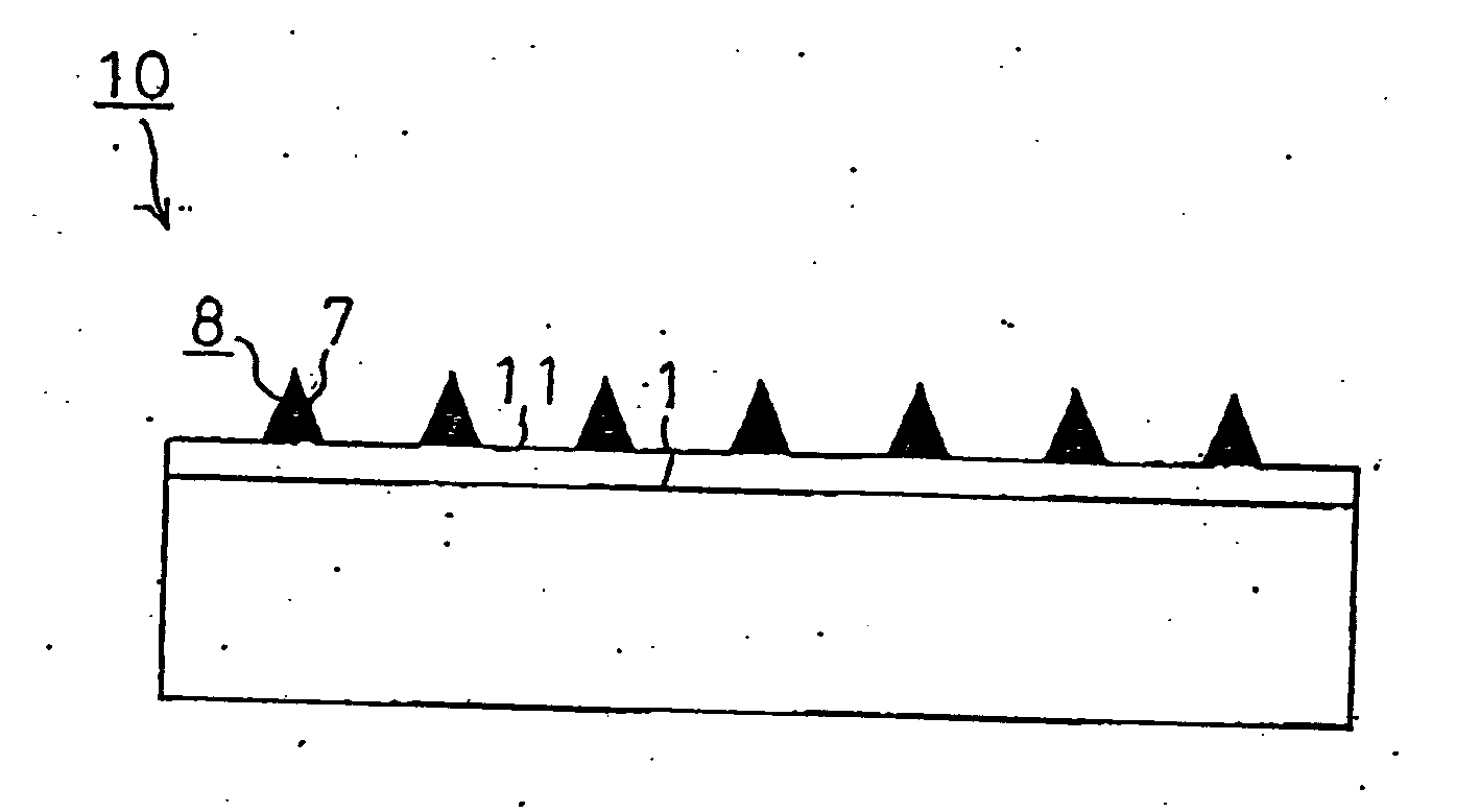
[0085] Next, in EXAMPLE 2, the transmission factor / the reflection factor of the TE polarized light and the TM polarized light were calculated on the wire grid polarizer 10 shown in FIG. 7 in the same manner as EXAMPLE 1. In the wire grid polarizer 10, a low-refractive-index layer 11 was formed on the light-transmitting substrate 1 having a high refractive index, and a wire grid structural body 8 with a taper-shape cross section was formed thereon.

[0086] More specifically, calculation was carried out on assumption that 20 nm of SiO2 layer as the low-refractive-index layer 11 was formed on the light-transmitting substrate 1 made of SF-6 (wavelength: λ=0.65 μm, refractive index: 1.797), a product of SCHOTT, and the wire grid structural body 8 in the same taper shape as that of EXAMPLE 1 was formed thereon.

[0087] As a result, the wave dependency of the polarization extinction ratio as shown in FIG. 13 was obtained.

[0088] As can be seen from FIG. 13, the absolute value of the polariza...


PUM


Abstract

An object is to provide a wire grid polarizer with an excellent optical property, which enables to maintain the polarization extinction ratio high and level in the broadband wavelength region with a simple structure. A wire grid polarizer of the present invention comprises, a wire grid structural body in which a plurality of metal wires are formed and arranged at a certain period in a direction orthogonal to a longitudinal direction of the metal wires on a light-transmitting substrate, for transmitting only a specific linearly polarized light out of linearly polarized lights being orthogonal to each other, which make incident to the wire grid structural body, wherein a cross-sectional shape of the metal wire, which is orthogonal to the longitudinal direction, has a taper shape.

Description

BACKGROUND OF THE INVENTION [0001] 1. Field of the Invention [0002] The present invention relates to a wire grid polarizer and, more specifically, to a wire grid polarizer which is preferably used as a polarizing beam splitter for separating linearly polarized lights being orthogonal to each other by transmitting or reflecting the light, in a light pickup optical system, an optical fiber communication optical system, a projection-type liquid crystal projector, a light-receiving sensor optical system and the like. [0003] 2. Description of the Related Art [0004] Conventionally, there have been various types of structures known as polarizer which transmits only linearly polarized light with a specific polarization component out of two linearly polarized lights being orthogonal to each other and absorbs or reflects the other polarization component. [0005] Above all, recently, a type of polarizer shown in FIG. 1 as a wire grid polarizer 4 has drawn an attention as the one which exhibits ...

Claims


Application Information

Patent Timeline
IPC IPC(8): G02B5/30
CPCG02B5/3058
Inventor SUGANUMA, TAKAYOSHI
Owner ENPLAS CORP
Why Eureka
Try Eureka