Compression zone recording head

a compression zone and recording head technology, applied in the field of magnetic tape recording heads, can solve the problems of excessive wear on the surface of the transducer, and achieve the effect of lowering the cost of fabrication and flying heigh

Inactive Publication Date: 2005-06-16
IBM CORP
View PDF12 Cites 28 Cited by
  • Summary
  • Abstract
  • Description
  • Claims
  • Application Information

AI Technical Summary

Benefits of technology

[0010] In accordance with the principles of the present invention, there is disclosed a compression zone recording head comprising a flat contour, or alternatively, a shallow contour head having a thin closure preferably formed of conducting material. The recording tape wraps over the deposited closure and after a short time wears into intimate rubbing contact with the recording elements. The edge of the wafer holding the recording elements provides the required durable support of the recording tape. Thus, the tape contacts the recording elements in a “compression zone” at the leading or t...

Problems solved by technology

However, the development of small footprint, higher performance tape drive systems has created various problems in the design of a tape head assembly for use in such sys...

Method used


Image

  • Compression zone recording head
  • Compression zone recording head
  • Compression zone recording head

Examples


first embodiment

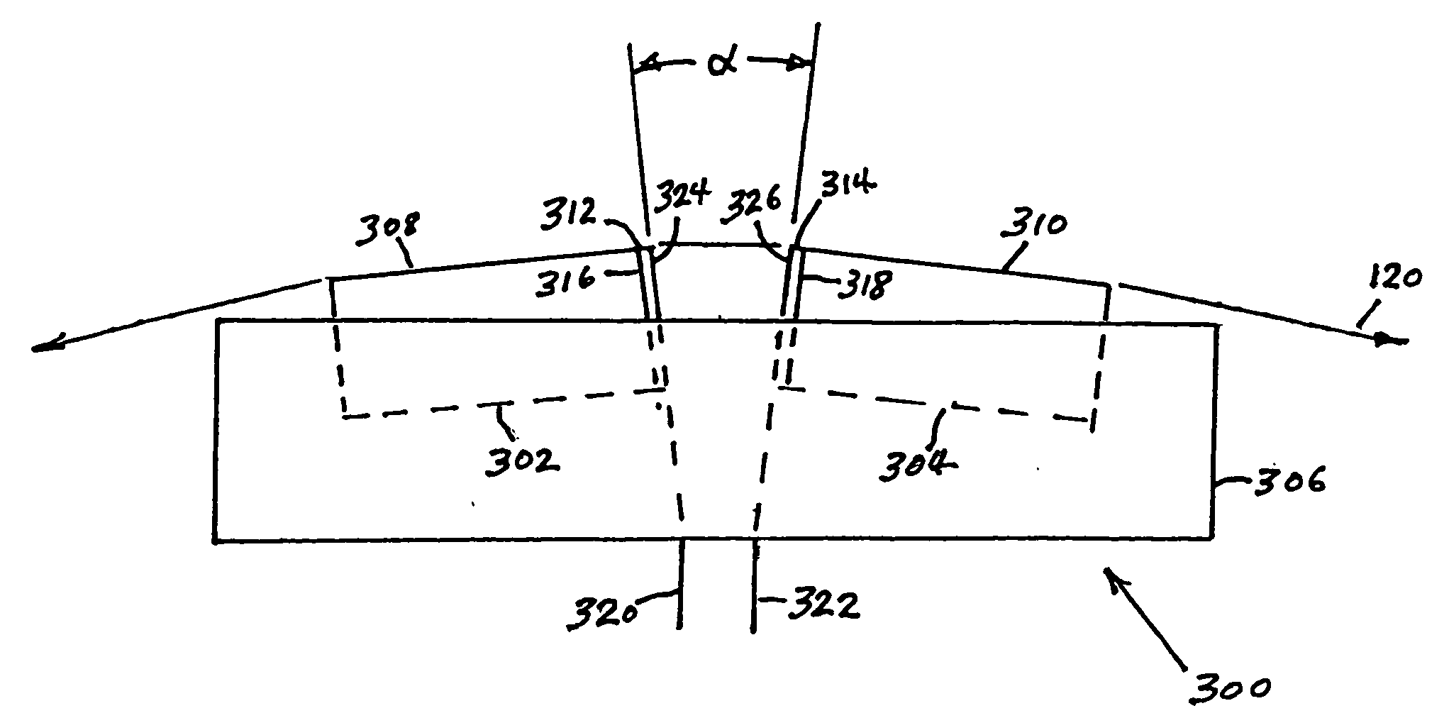
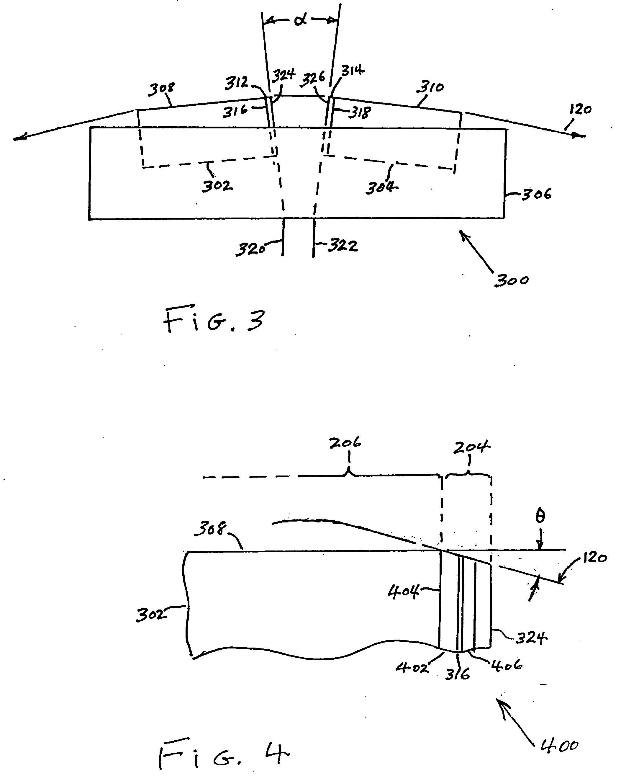
[0026]FIG. 3 illustrates a compression zone recording head 300 according to the present invention. The head 300 comprises rowbar substrates 302 and 304 of a wear resistant material, such as the substrate ceramic typically used in magnetic disk drive heads, are fixed in a carrier 306 at a small angle α with respect to each other. The ceramic rowbar substrates 302 and 304 are provided with flat transducing surfaces 308 and 310. Rows of transducers 316 and 318 are provided at the surfaces of gaps 312 and 314. Electrical connection cables 320 and 322 connect the transducers to the read / write channel of the associated tape drive. The rows of transducers are protected by thin closures 324 and 326 made of a layer of hard, preferably conductive, material such as Al—Fe—Si (Sendust) deposited over the row of transducers, or alternatively of a layer of Al—O—Ti—C, Zr—O—Ti, Si—N, Si—C or Zr—O deposited or bonded to the row of transducers.

[0027]FIG. 4 illustrates an enlarged portion 400 of the ro...

second embodiment

[0029]FIG. 5 illustrates a compression zone recording head 500 according to the present invention. The head 500 comprises rowbar substrates 502 and 504 of a wear resistant material, such as the substrate ceramic typically used in magnetic disk drive heads, fixed in a carrier 506. The ceramic rowbar substrates 502 and 504 are provided with flat transducing surfaces 508 and 510 that lie in the same plane, or alternatively, are separated from one another and form a small angle (not shown) with respect to each other. Rows of transducers 516 and 518 are provided on the surfaces of gaps 512 and 514 at the outer edges of substrates 502 and 504. Electrical connection cables 520 and 522 connect the transducers to the read / write channel of the associated tape drive. The rows of transducers 516 and 518 are protected by thin closures 524 and 526, respectively, made of a layer of hard, preferably conductive, material such as Al—Fe—Si (Sendust) deposited over the insulation layer on the row of tr...


PUM


Abstract

A compression zone recording head is provided having the recording tape in contact or near contact with the recording read/write transducer elements in a compression zone of the tape passing over a transducing surface. The compression zone recording head comprises a flat or shallow contour head having a thin, hard, preferably conducting closure to provide wear protection to the transducers. In one embodiment of the invention, the transducers are located in a compression zone region where the recording tape contacts an edge of the transducing surface at a controlled wrap angle. In another embodiment, the transducers are located in a canopy zone region of the transducing surface due to bending of the tape due to the overwrap. The protective closure is preferably made of sputter deposited Al—Fe—Si, or alternatively of a deposited or bonded layer of Al—Fe—Si, Al—O—Ti—C, Zr—O—Ti, Si—N, Si—C or Zr—O.

Description

BACKGROUND OF THE INVENTION [0001] 1. Field of the Invention [0002] This invention relates to magnetic tape recording heads, and more particularly to a compression zone recording head. [0003] 2. Description of the Related Art [0004] In magnetic storage systems, data is read from and written onto magnetic recording media utilizing magnetic transducers commonly referred to as magnetic heads. Data is written on the magnetic recording media by moving a magnetic recording head to a position over the media where the data is to be stored. The magnetic recording head then generates a magnetic field, which encodes the data into the media. Data is read from the media by similarly positioning the magnetic read head and then sensing the magnetic field of the magnetic medial. Read and write operations are independently synchronized with the movement of the media to ensure that the data can be read from and written to the desired location on the media. [0005] An important and continuing goal in t...

Claims


Application Information

Patent Timeline
IPC IPC(8): G11B5/008G11B5/10G11B5/48
CPCG11B5/4893G11B5/00826
Inventor BISKEBORN, ROBERT GLENNLIANG, JASON
Owner IBM CORP
Why Eureka
Try Eureka