Device and method for pumping fluids employing the movement of gas bubbles in microscale

a gas bubble and micro-scale technology, applied in the direction of snap-action arrangements, instruments, and the details of the semiconductor/solid-state device, can solve the problems of affecting the flow rate of the pump, the method is not reliable, and the diffusion of particles may be blocked by the nozzle, so as to eliminate solid friction and heat loss

Inactive Publication Date: 2005-06-16
SAMSUNG ELECTRONICS CO LTD
View PDF7 Cites 25 Cited by
  • Summary
  • Abstract
  • Description
  • Claims
  • Application Information

AI Technical Summary

Benefits of technology

[0016] The present invention has been developed in order to solve the above drawbacks and other problems associated with conventional arrangements. An aspect of the present invention is to provide micro-fluidic device and pumping method for bio-fluids or chemical liquids through micro channels while eliminating solid frictions and heat loss.

Problems solved by technology

The above method has a disadvantage of degrading reliability where the pump runs for an extended time since small actuating values employed for net fluid movements, and preventing reverse flows, are delicate parts that have to be very carefully manufactured.
Delicate parts like those can be damaged during extended pump running times.
This micro pump has some disadvantages such as particles possibly blocking the nozzle diffusion paths and damage to the pumping chamber due to bubble-collapsing pulses.
That is, changing the location where power is applied to heat sources produces the movement of vapor bubbles, which results in the pumping of liquid.
The above pump requires a high power consumption of more than 10 Watts, features slow thermal responses, and requires manual control of phase growth.
One severe disadvantage of the aforementioned pumping principles and pumps is that heating the pumped fluids to its boiling point can not be applied to most pumped fluids and corresponding micro-fluidic devices.
The drawback to this micro pump goes to specific structures of a manual pressure-applying mechanism and micro channels.
Other disadvantages of such a pumping principle include a complicated manufacturing process and conductive heat loss.
The inaccurate control on bubble transportation through channels and heaters requires a certain countermeasure on temperature control and packaging.

Method used


Image

  • Device and method for pumping fluids employing the movement of gas bubbles in microscale
  • Device and method for pumping fluids employing the movement of gas bubbles in microscale
  • Device and method for pumping fluids employing the movement of gas bubbles in microscale

Examples


Embodiment Construction

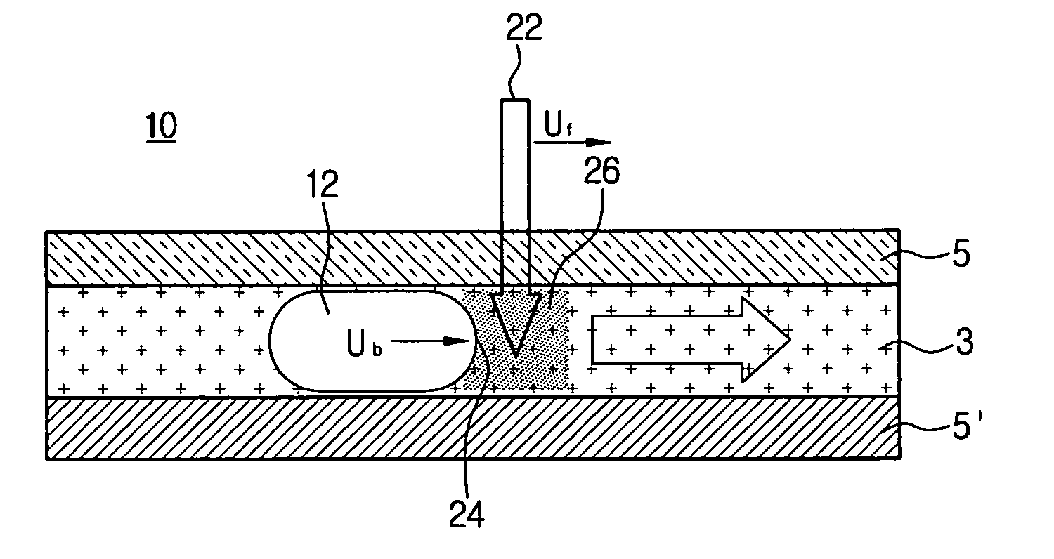
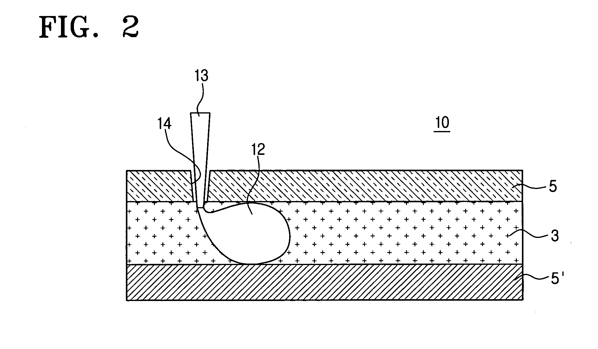
[0031] The micro fluid pumping device and method according to the present invention can pump bio-fluids of liquid chemicals based on active bubbles through micro channels without any mechanical transport parts or resistance heaters since the device and method can precisely carry out the controls on gas bubbles by use of emitted light beams on microscale.

[0032] Hereinafter, the present invention will be described in detail with reference to the accompanying drawings. During the description of the present invention, like parts and areas are designated with like reference numerals even in different drawings.

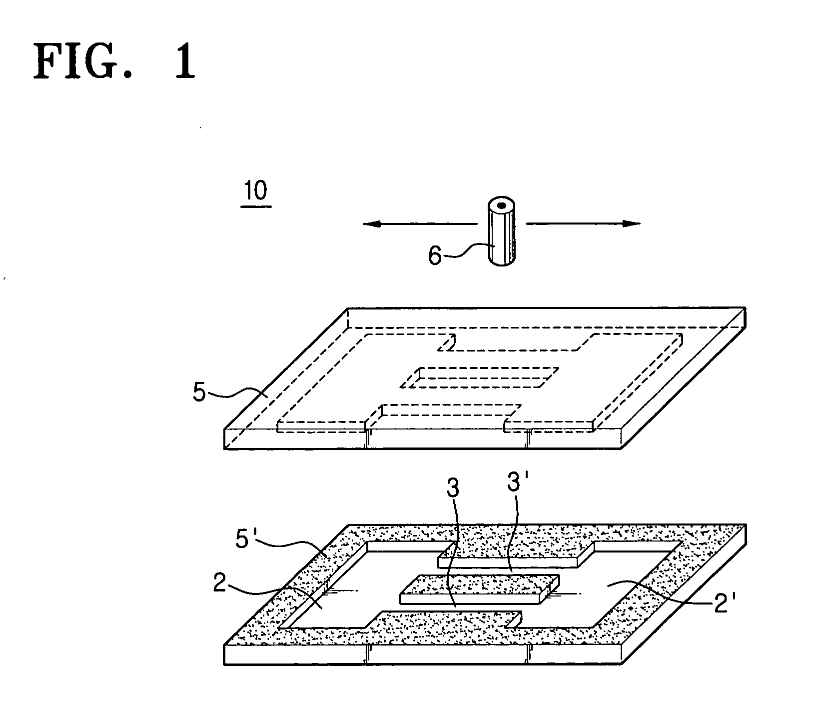
[0033]FIG. 1 is a perspective view for schematically showing a micro fluid pumping device according to one embodiment of the present invention. A micro fluid pumping device 10 has cover 5 and substrate 5′ on which upper and lower patterns are formed for two fluid reservoirs 2 and 2′ and two channels 3 and 3′ respectively, and a light source module 6 installed to emit light beams m...


PUM

PropertyMeasurementUnit
power consumptionaaaaaaaaaa
conversion consumption timeaaaaaaaaaa
lengthaaaaaaaaaa

Abstract

The present fluid pumping method for micro-fluidic devices uses gas bubbles to move fluid by light beams. The light beams are emitted to the fluid near the gas bubble through an optically transparent cover and correspondingly heat the fluid in the micro channels. The liquid temperature variation changes the surface tension of the gas bubble near the heated fluid side, therefore, a pressure gradient between the end portions of the gas bubble generates accordingly. By moving the light beams, the moved pressure difference will be achieved, which will drive the gas bubbles and pump the fluid. Such a fluid pumping can simplify the structure of a micro-fluidic device and eliminate heat loss because of using a controllable light beam.

Description

CROSS-REFERENCE TO RELATED APPLICATIONS [0001] This application claims benefit under 35 U.S.C. § 119 from Korean Patent Application No. 2003-91467, filed on Dec. 15, 2003, the entire content of which is incorporated herein by reference.BACKGROUND OF THE INVENTION [0002] 1. Field of the Invention [0003] The present invention relates to a device and method for pumping fluids, and more particularly, to a device and method for pumping fluids employing the movement of gas bubbles through channels in microscale. [0004] 2. Description of the Related Art [0005] A micro-fluidic system refers to a system combining fluid dynamics and Micro-Electro-Mechanical Systems (MEMS), which can control fluid flows in micro units. For example, systems are being developed to perform tasks such as extracting DNA from very small test samples, checking gene mutation, and so on. [0006] Pumping fluids such as bio-fluids and chemical solutions through microscale channels is closely related to future micro-fluidi...

Claims


Application Information

Patent Timeline
Patent Type & Authority Applications(United States)
IPC IPC(8): B01J4/00B81B5/00G01N37/00B81B7/02F04B9/00F04B19/00F04B19/24
CPCF04B19/24F04B19/006B81B7/02
Inventor CHO, HYE-JUNG
Owner SAMSUNG ELECTRONICS CO LTD
Why Eureka
Try Eureka