Honeycomb structural body, method of manufacturing the structural body, and catalyst body using the structural body

Active Publication Date: 2005-06-16
NGK INSULATORS LTD
View PDF3 Cites 21 Cited by
  • Summary
  • Abstract
  • Description
  • Claims
  • Application Information

AI Technical Summary

Benefits of technology

[0007] [1] A honeycomb structure comprising: a cell structural part including a plurality of cells partitioned by partition walls in a honeycomb shape to form flow paths allowing a fluid to flow therein; and an outer wall disposed on an outer peripheral surface of the cell structural part, characterized in that an outermost peripheral cell positioned in an outermost periphery of the cell structural part and a predetermined number of cells (outer peripheral cells) positioned in an inner direction from the outermos

Problems solved by technology

Since a catalytic activity of the catalyst for use in the honeycomb structure (catalyst body) supporting the catalyst usually increases in a high-temperature region, an automobile is run in a low state of the catalytic activity, and an insufficiently purified exhaust gas is exhausted from start of the running of the automobile until a temperature of the honeycomb structure rises.
However, the reduced bulk density by the thinning of the partition wall of the cell and the increasing of the porosity has caused a drop in mechanical strength of the honeycomb structure.
As described also in Japanese Patent Application Laid-Open No. 3-275309, there has been a problem that a cell partition wall in an outer peripheral part of the honeycomb structure is deformed under the weight of the ho

Method used


Image

  • Honeycomb structural body, method of manufacturing the structural body, and catalyst body using the structural body
  • Honeycomb structural body, method of manufacturing the structural body, and catalyst body using the structural body
  • Honeycomb structural body, method of manufacturing the structural body, and catalyst body using the structural body

Examples


Embodiment Construction

[0033] Embodiments of the present invention will be described hereinafter concretely with reference to the drawings, but it should be understood that the present invention is not limited to the following embodiments and that modifications, improvements and the like of designs are appropriately added without departing from the scope of the present invention based on ordinary knowledge of a person skilled in the art.

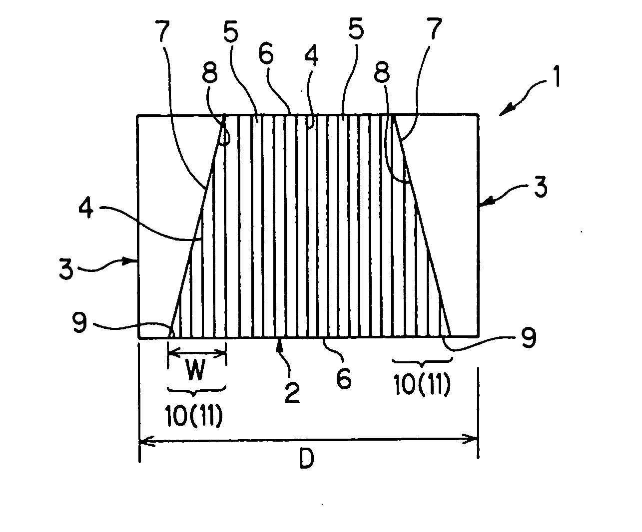
[0034]FIG. 1 is a sectional view of a honeycomb structure cut by a plane including a central axis in one embodiment of the present invention. In FIG. 1, a honeycomb structure 1 is constituted of a cell structural part 2 having a truncated cone shape, and an outer wall 3 disposed on an outer peripheral surface 7 of the cell structural part 2 (corresponding to a side surface of a truncated cone). An outer periphery of the outer wall 3 is formed into a cylindrical shape, and an inner peripheral surface 8 of the outer wall 3 extends along the outer peripheral surface 7 of the...


PUM

PropertyMeasurementUnit
Fractionaaaaaaaaaa
Thicknessaaaaaaaaaa
Shrinkageaaaaaaaaaa

Abstract

A honeycomb structure of the present invention is a honeycomb structure 1 including: a cell structural part 2 including a plurality of cells 6 partitioned by partition walls 4 in a honeycomb shape to form flow paths allowing a fluid to flow therein; and an outer wall 3 disposed on an outer peripheral surface 7 of the cell structural part 2, characterized in that an outermost peripheral cell 9 of the cell structural part 2 and a predetermined number of cells positioned in an inner direction from the outermost peripheral cell among the cells 6 are sealed by an inner peripheral surface of the outer wall 3 in an end portion and/or an intermediate portion of at least one of the outermost peripheral cell and the outer peripheral cell in a central axis direction to constitute shielded cells 11, a temperature rising time of the cell structural part 2 after start of an operation shortens, and a catalytic activity can be enhanced in a short time when a catalyst is supported.

Description

TECHNICAL FIELD [0001] The present invention relates to a honeycomb structure, a method of manufacturing the honeycomb structure, and a catalyst body using the honeycomb structure. In more detail, the present invention relates to a honeycomb structure in which an outer wall is disposed on an outermost side of the honeycomb structure (on an outer peripheral surface of a cell structural part) and in which a temperature rising time for the cell structural part after start of an operation shortens and in which a catalytic activity can be enhanced in a short time when a catalyst is supported, a method of manufacturing the honeycomb structure, and a catalyst body using the honeycomb structure. BACKGROUND ART [0002] In recent years, to cope with automobile exhaust gas regulations which have been reinforced year by year, a honeycomb structure (catalyst body) supporting a catalyst has been used in order to remove nitrogen oxide, sulfur oxide, hydrogen chloride, hydrogen carbide, carbon monox...

Claims


Application Information

Patent Timeline
IPC IPC(8): F01N3/02B01D39/14B01D39/20B01D46/00B01D46/24B01D53/86B01J35/04B21D47/00C04B38/00F01N3/022F01N3/28F01N13/14
CPCB01D39/2068Y10T428/24149B01D46/2451B01D46/2455B01D46/2459B01D46/2466B01D2046/2492B01J35/04F01N3/0222F01N3/2803F01N3/2828F01N3/2853F01N13/14F01N2450/02Y02T10/20B01D46/0036Y02T10/12B01D46/2482B01D46/247B01D46/2462
Inventor ICHIKAWA, YUKIHITO
Owner NGK INSULATORS LTD
Why Eureka
Try Eureka