High convection home hemodialysis/hemofiltration and sorbent system

a hemodialysis and sorbent system technology, applied in the field of medical treatments, can solve the problems of high degree of intentional backfiltration, achieve the effect of convenient setting up of sterile blood therapy system, and improving the effectiveness of renal failure blood treatment therapy

Inactive Publication Date: 2005-06-16
BAXTER HEALTHCARE SA +1
View PDF71 Cites 560 Cited by
  • Summary
  • Abstract
  • Description
  • Claims
  • Application Information

AI Technical Summary

Benefits of technology

[0032] It is therefore an advantage of the present invention to provide a hemodialysis, hemofiltration or hemodiafiltration system usable in a home or clinic setting.
[0033] It is another advantage of the present invention to provide a cassette-based hemofiltration / hemodiafiltration system, which enables a patient at home to easily set up a sterile blood therapy system.
[0034] It is another advantage of the present invention to improve the effectiveness of renal failure blood treatment therapy.
[0035] Moreover, it is an advantage of the present invention to provide a renal failure blood therapy that employs convective and diffusive modes of clearance.
[0036] Still further, it is an advantage of the present invention to provide a renal failure blood therapy in which both diffusive and convective clearance modes are provided and wherein the percentage use of either mode can be varied.
[0037] Further still, it is an advantage of the present invention to provide a cassette-based blood therapy that is configurable in the field to perform either hemodialysis, enhanced convection hemodialysis, hemofiltration or hemodiafiltration.

Problems solved by technology

Due to the restriction between the filters, a positive pressure is built in the venous dialyzer, causing a high degree of intentional backfiltration.

Method used


Image

  • High convection home hemodialysis/hemofiltration and sorbent system
  • High convection home hemodialysis/hemofiltration and sorbent system
  • High convection home hemodialysis/hemofiltration and sorbent system

Examples


example

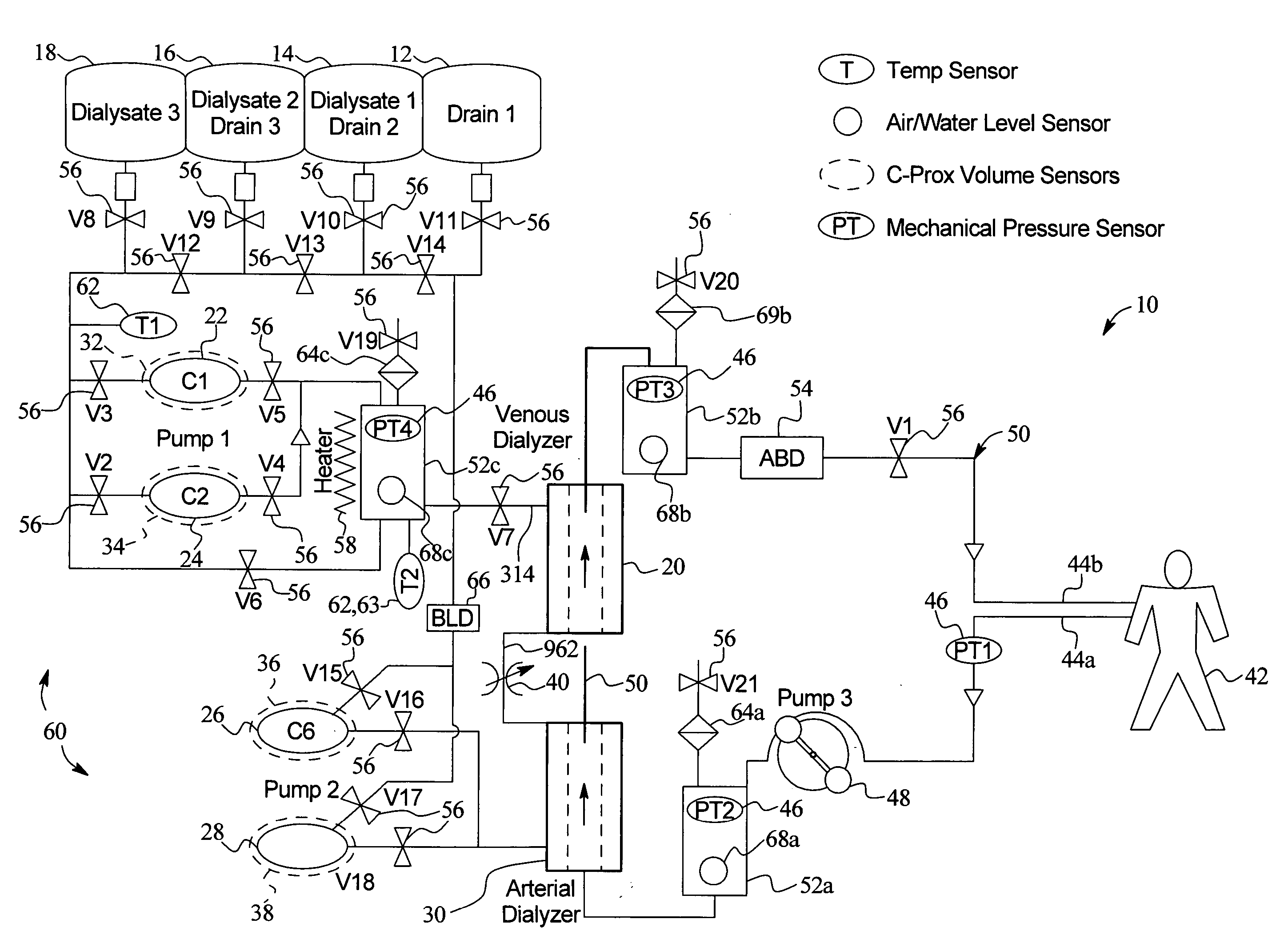
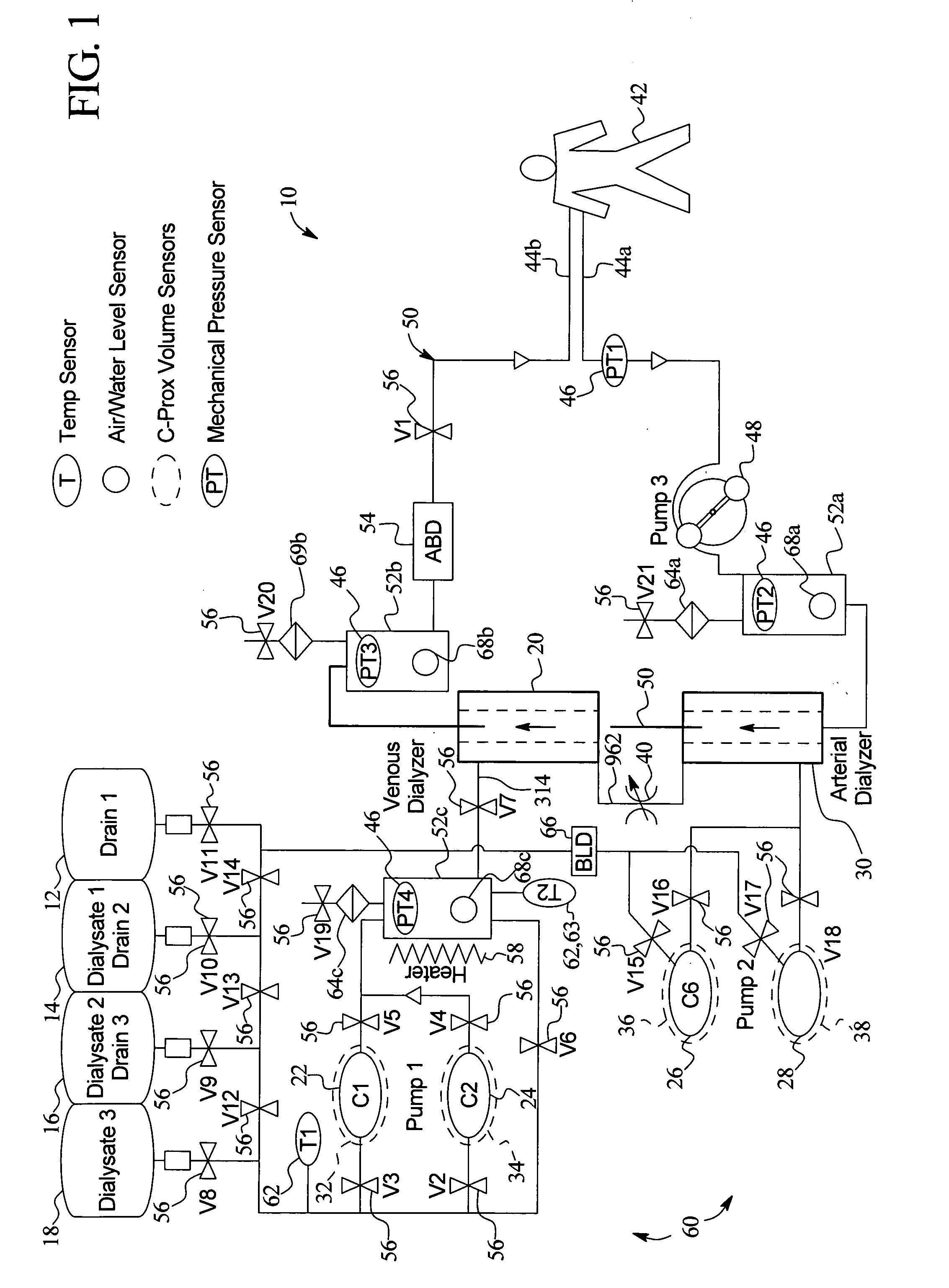
[0085] The following example further illustrates one preferred therapy for the present invention. In the example, pumps 22 and 24 of Pump Set 1 infuse eighteen liters of dialysate from sources 14, 16 and 18 over two hours. Of that volume, one hundred ml / min of dialysate is backfiltered into the patients' blood circuit 50 through the membrane walls of venous dialyzer 20. Fifty ml / min of dialysate passes through the venous dialyzer 20, restriction 40 and into venous dialyzer 30. Pumps 26 and 28 of Pump Set 2 remove the total of eighteen liters of dialysate from bags 14, 16 and 18 plus any desired amount of fluid from the patient. Over two hours, twelve liters (100 ml / min multiplied by 120 minutes) of dialysate is backfiltered into the patient's blood through the venous dialyzer 20. Pumps 26 and 28 of Pump Set 2 remove that twelve liters, the six liters of dialysate that is not backfiltered into blood circuit 50 plus any fluid ultrafiltered from the patient.

[0086] The addition and rem...


PUM


Abstract

A system, method and apparatus for performing a renal replacement therapy is provided. In one embodiment, two small high flux dialyzers are connected in series. A restriction is placed between the two dialyzers in the dialysate flow path. The restriction is variable and adjustable in one preferred embodiment. The restriction builds a positive pressure in the venous dialyzer, causing a high degree of intentional backfiltration. That backfiltration causes a significant flow of dialysate through the high flux venous membrane directly into the patient's blood. That backfiltered solution is subsequently ultrafiltered from the patient from the arterial dialyzer. The diffusion of dialysate into the venous filter and removal of dialysate from the arterial dialyzer causes a convective transport of toxins from the patient. Additionally, the dialysate that does not diffuse directly into the patient but instead flows across the membranes of both dialyzers provides a diffusive clearance of waste products.

Description

PRIORITY CLAIM [0001] This application claims the benefit of U.S. Provisional Patent Application No. 60 / 517,730, filed Nov. 5, 2003, entitled “High Convection Home Hemodialysis / Hemofiltration And Sorbent System”, the entire contents of which are hereby incorporated by reference and relied upon.BACKGROUND OF THE INVENTION [0002] The present invention relates generally to medical treatments. More specifically, the present invention relates to medical fluid treatments, such as the treatment of renal failure and fluid removal for congestive heart failure. [0003] Hemodialysis (“HD”) in general uses diffusion to remove waste products from a patient's blood. A diffusive gradient that occurs across the semi-permeable dialyzer between the blood and an electrolyte solution called dialysate causes diffusion. Hemofiltration (“HF”) is an alternative renal replacement therapy that relies on a convective transport of toxins from the patient's blood. This therapy is accomplished by adding substitut...

Claims


Application Information

Patent Timeline
Patent Type & Authority Applications(United States)
IPC IPC(8): A61M1/16A61M1/34B01D61/58
CPCA61M1/1696A61M1/3621A61M1/3643A61M2205/12A61M2205/3553A61M2205/3561A61M2205/3584A61M2205/505A61M1/16A61M2205/502A61M1/1607A61M1/1633A61M1/1635A61M1/288A61M1/3431A61M1/3434A61M1/3458A61M1/3646A61M1/3649A61M1/365A61M2205/18A61M2205/15A61M2202/0413A61M1/3626A61M2205/3368A61M2205/3327A61M2205/75A61M1/342A61M1/3427A61M1/3444A61M1/3451A61M2205/3317A61M2205/3324A61M2205/3393A61M1/1613A61M1/341A61M1/3647A61M1/3652A61M1/1668A61M1/167A61M1/1672A61M2205/3334A61M1/3465A61M1/3644A61M1/166A61M1/3437A61M2205/3331A61M1/3486A61M1/3417A61M60/113A61M60/279A61M60/43A61M60/258A61M2205/127A61M60/851A61M60/37A61M60/508A61M60/847A61M60/849A61M1/155A61M1/154A61M1/15625A61M1/362261A61M1/1561A61M1/36225A61M1/1565A61M1/1522A61M1/1563A61M1/362265A61M1/3401A61M1/153A61M1/36224A61M1/362223A61M1/1601A61M1/1621A61M2205/13A61M2205/276A61M1/1656A61M1/1629A61M1/267A61M1/3472A61M1/3468A61M1/3656A61M1/3624A61M1/3627A61M2205/3337A61M2205/3344A61M2205/3379A61M2205/52
Inventor KELLY, THOMASCHILDERS, ROBERT W.BUSBY, DONROGER, RODOLFOSAYYID, WALEED MUTASEM ELDIN, SHAHID
Owner BAXTER HEALTHCARE SA
Why Eureka
Try Eureka