Carrier body and method

a carrier body and cutting tool technology, applied in the direction of liquid surface applicators, coatings, metal material coating processes, etc., can solve the problems of affecting the performance of cutting tools, reducing toughness, and reducing tool li

Inactive Publication Date: 2005-06-23
SECO TOOLS AB +1
View PDF6 Cites 306 Cited by
  • Summary
  • Abstract
  • Description
  • Claims
  • Application Information

AI Technical Summary

Benefits of technology

[0011] It is an object of the present invention to provide a carrier body t

Problems solved by technology

However, during coating operation not only the tools are coated but also the support on which the cutting inserts rest resulting in that the inserts grow together with the surfaces of the support.
These contact marks are not only a cosmetic problem.
If they appear on surfaces actually in operation during the metal cutting operation they may lead to a decreased tool life.
An erroneously positioned cutting insert will negatively influence the performance of the cutting tool, i.e. decreased toughness, reduced accuracy and surface finish of the work piece.
Therefore, a batch loading system which necessarily needs different arrangement for different cutting insert geometries in order to get a uniform loading density will never work very rational in a production environment focused on low cost and short lead time.
Using this method for CVD and/or MTCVD would get several disadvantage as it is primarily not a universal method, as described above, since different geometries of cutting inserts will need different set-up of the pins.
Secondly, a hole is needed on the cutting inserts.
Thirdly, when applying thick CVD and/or MTCVD layers the cutting inserts will probably get heavily stu

Method used


Image

  • Carrier body and method
  • Carrier body and method
  • Carrier body and method

Examples


example 1

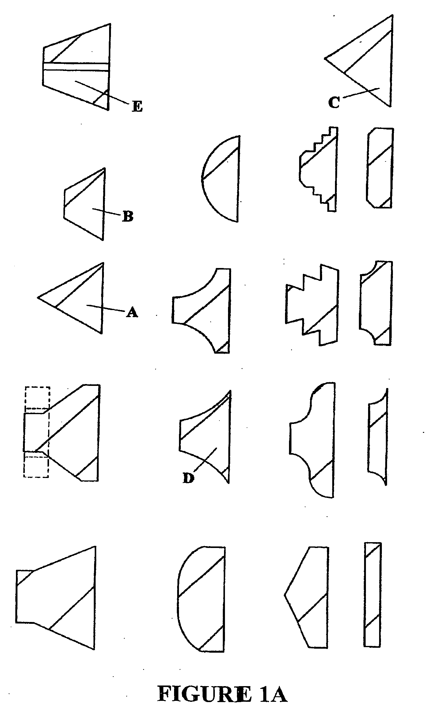
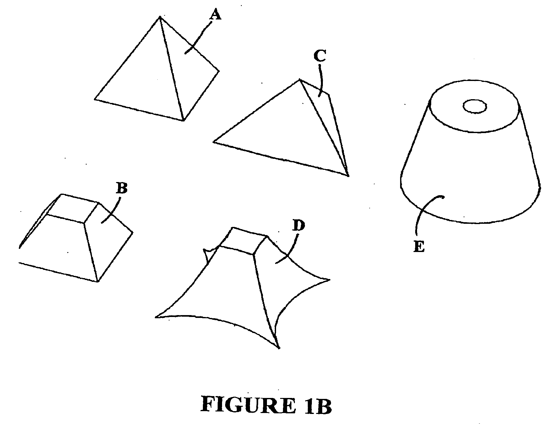
[0040] Four-sided pyramids with straight corners, see FIGS. 1A and 1B variant A, with a base of 10 mm side and a height of 7 mm were produced of the MAX phase material Ti3SiC2 having small amounts of impurities, hereafter called variant A-MAX, and of graphite, called variant A-graphite. The pyramids were positioned on a flat graphite tray with regularly positioned holes of diameter 3 mm. The pyramids were pre-coated with CVD and MTCVD layers of Ti(C,N)+Al203+TiN of a total thickness of 25 μm. Cemented carbide cutting inserts of geometry CNMG120408 for P25 application area were positioned on the every pyramid of the two variants. Totally 100 pyramids per variant were used.

[0041] CVD / MTCVD production-coating of Ti(C,N)+A1203+TiN with an approximately 15 μm total coating thickness was deposited on the cutting inserts.

[0042] After coating all cutting inserts were examined using a stereo microscope in 10×magnification for marks. The marks were classified with respect to: no visible mar...

example 2

[0045] Single-sided cemented carbide cutting inserts of geometry XOMX0908-ME06 with composition 91 wt. % WC−9 wt. % Co were used. Before deposition the uncoated substrates were cleaned.. A CVD production-coating of Ti(C,N)+Al203+TiN with an approximately 5 μm total coating thickness was deposited on the cutting inserts.

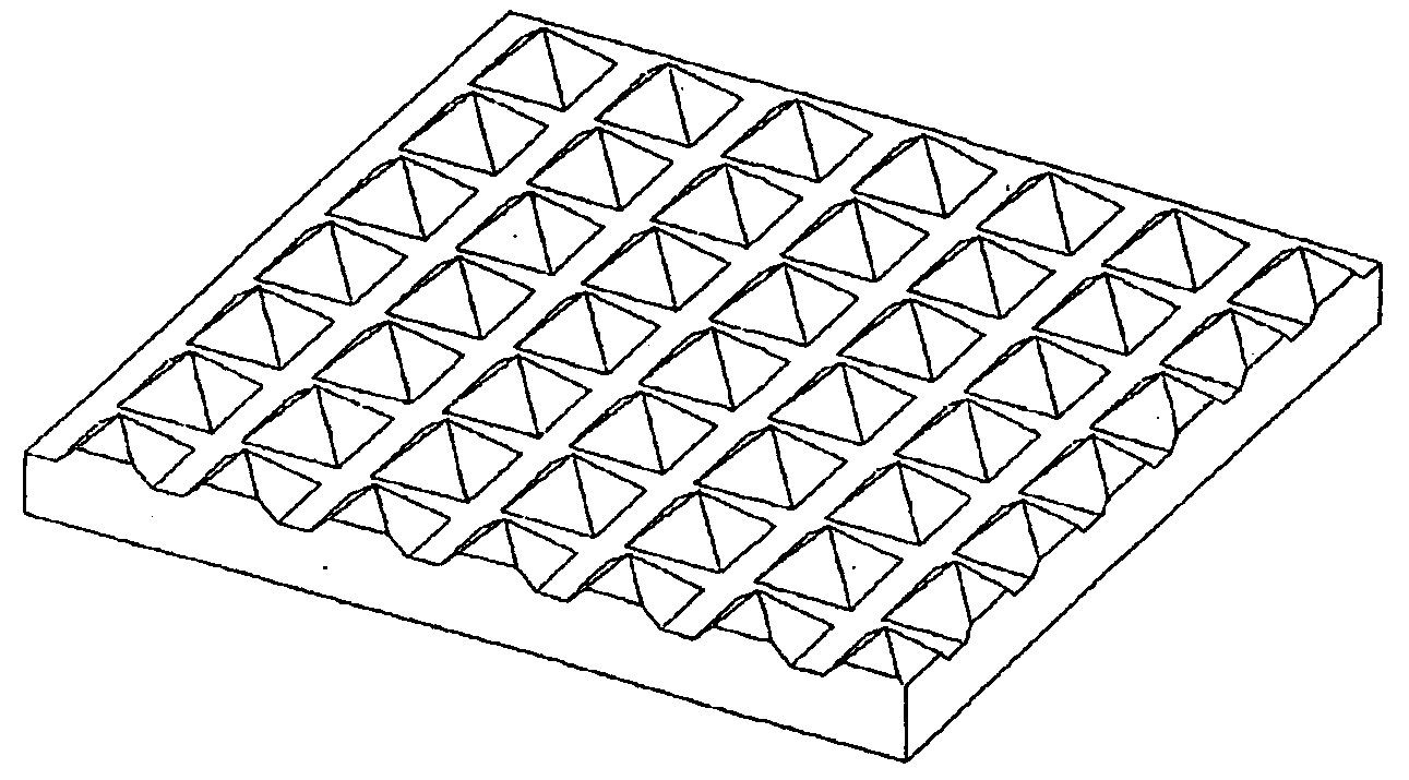
[0046] The cutting inserts were positioned directly on a flat tray, similar to the one in FIG. 1A down to the right but larger. The tray consisted of a graphite carrier body comprising essentially Ti3SiC2 having small amounts of impurities, variant A-MAX, and of graphite, variant A-graphite. The thickness of the sectors was 5 mm. The sectors had been pre-coated with a CVD and MTCVD coating of Ti(C,N)+Al203+TiN to a total coating thickness of 20 μm before the test in production coating. Totally 100 cutting inserts per variant were coated.

[0047] After production coating all cutting inserts were examined according to example 1.

[0048] Cutting inserts measured were coat...


PUM

PropertyMeasurementUnit
Thicknessaaaaaaaaaa
Areaaaaaaaaaaa

Abstract

The present invention relates to a method and a carrier body for coating cutting tools for chip removal. The carrier body is adapted to be used during coating of cutting tool inserts in a CVD and/or a MTCVD method. The carrier body is at least partially comprised of a material selected from the MAX phase family, i.e. Mn+1AXn (n=1,2,3) wherein M is one or more metals selected from the groups IIIB, IVB, VB, VIB and VIII of the periodic table of elements and/or their mixture, A is one or more metals selected from the groups IIIA, IVA, VA and VIA of the periodic table of elements and/or their mixture, and wherein X is carbon and/or nitrogen.

Description

BACKGROUND OF THE INVENTION [0001] The present invention relates to a carrier body and a method for coating cutting tools (indexable cutting inserts) for chip removal in accordance with the preambles of the appended independent claims. [0002] CVD (Chemical Vapour Deposition) deposited wear resistant layers, particularly of TiC, Ti(C,N), TiN and Al203 on cemented carbide cutting inserts have been industrially produced for 30 years. Details regarding the deposition condition of CVD and / or MTCVD (Moderate Temperature Chemical Vapour Deposition) layers and the design of CVD and / or MTCVD based layers have been extensively discussed in the literature as well as in patents. [0003] One of the major advantage of the CVD and / or MTCVD technique is the possibility of coating very large numbers of tools in the same batch, up to 30,000 cutting inserts depending on the size of the inserts and the equipment used, which gives a low production cost per insert with coating all-around the cutting inser...

Claims


Application Information

Patent Timeline
IPC IPC(8): C23C16/00C23C16/458
CPCC23C16/4581C23C16/458C23C16/00
Inventor EL-RAGHY, TAMERLAITILA, EDWARDPETTERSSON, LENAMALMQVIST, GUSTAV
Owner SECO TOOLS AB
Why Eureka
Try Eureka