
Mode converter device using omnidirectional reflectors

a mode converter and omnidirectional reflector technology, applied in the direction of optical waveguide light guide, instruments, nanotechnology, etc., can solve the problems of insufficient optical coupling efficiency, difficult to actually realize, and inability to achieve mode conversion based on typical tapering, etc., to achieve low loss coupling, high index contrast, and high optical coupling efficiency

Inactive Publication Date: 2005-06-23
SAMSUNG ELECTRONICS CO LTD
View PDF5 Cites 12 Cited by
  • Summary
  • Abstract
  • Description
  • Claims
  • Application Information

AI Technical Summary

Benefits of technology

[0013] The present invention provides an optical mode converter with increased coupling efficiency.
[0016] The exemplary embodiments of the present invention provide a novel mode-size converter designed to achieve minimum loss coupling between either an optical fiber or a low index difference waveguide and a high index contrast waveguide using omnidirectional reflectors. The exemplary embodiments of the present invention can realize a mode-size converter to achieve high optical coupling efficiency in both directions over a wide range of wavelength bands with a simple manufacturing process.

Problems solved by technology

However, for a high index contrast waveguide designed for a low price, ultraslim optical device, mode conversion cannot be achieved based on typical tapering since it has a very small mode size.
The optical mode converter configured so that the two tapered regions overlap each other is not only difficult to actually realize due to an extremely complicated manufacturing process, but also has not sufficiently high optical coupling efficiency (75% coupling efficiency at wavelength of 1.55 μm)

Method used


Image

  • Mode converter device using omnidirectional reflectors
  • Mode converter device using omnidirectional reflectors
  • Mode converter device using omnidirectional reflectors

Examples


Embodiment Construction

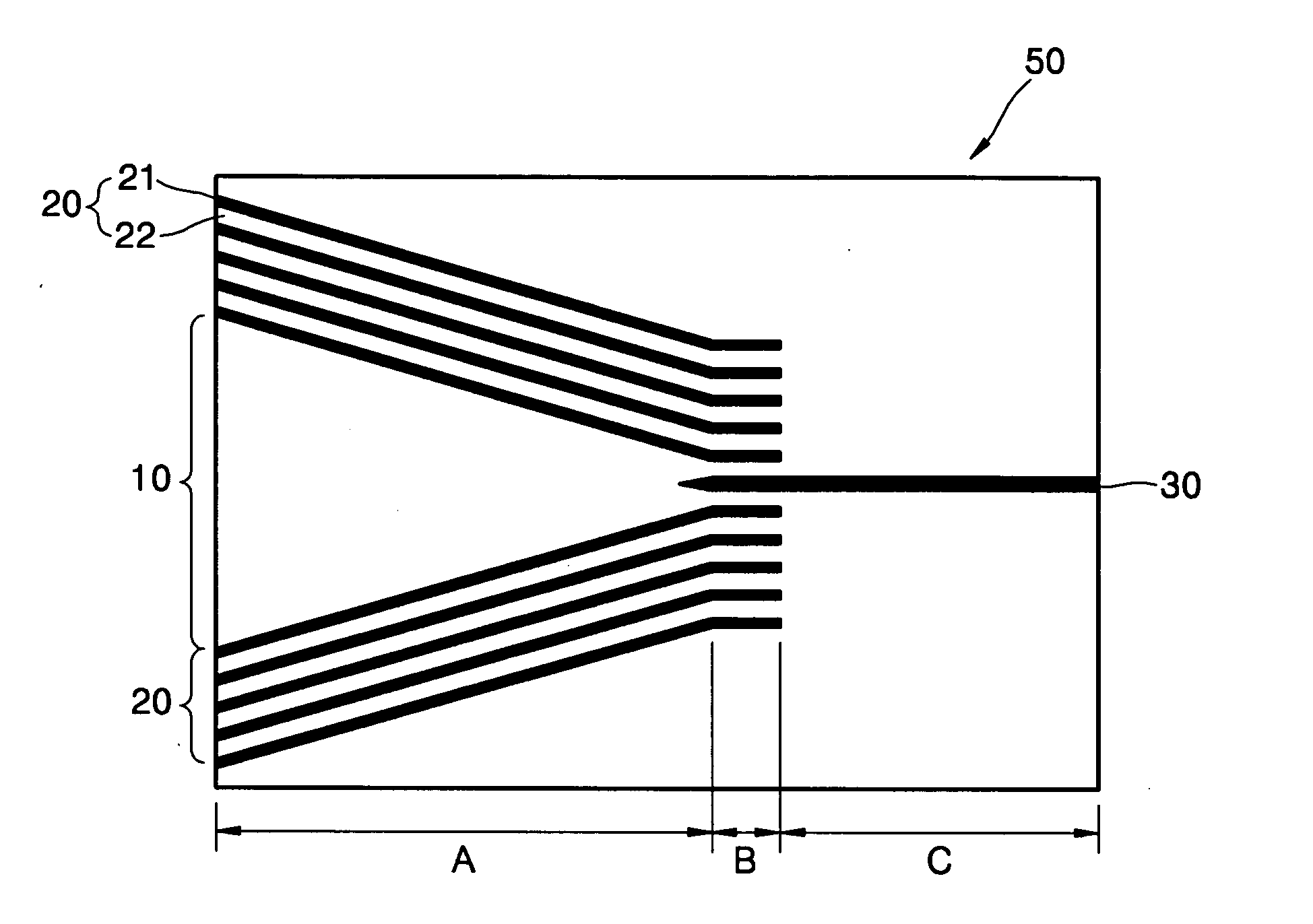
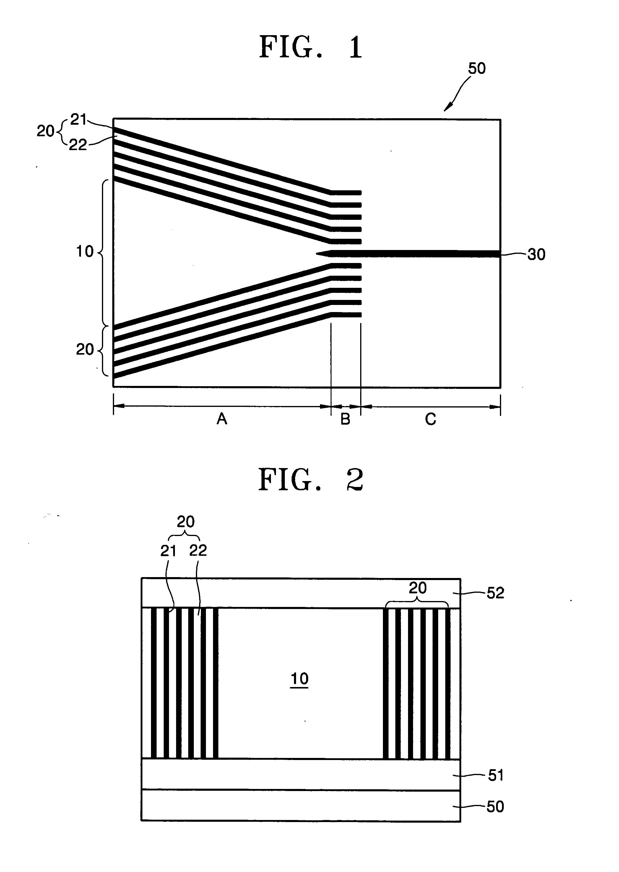
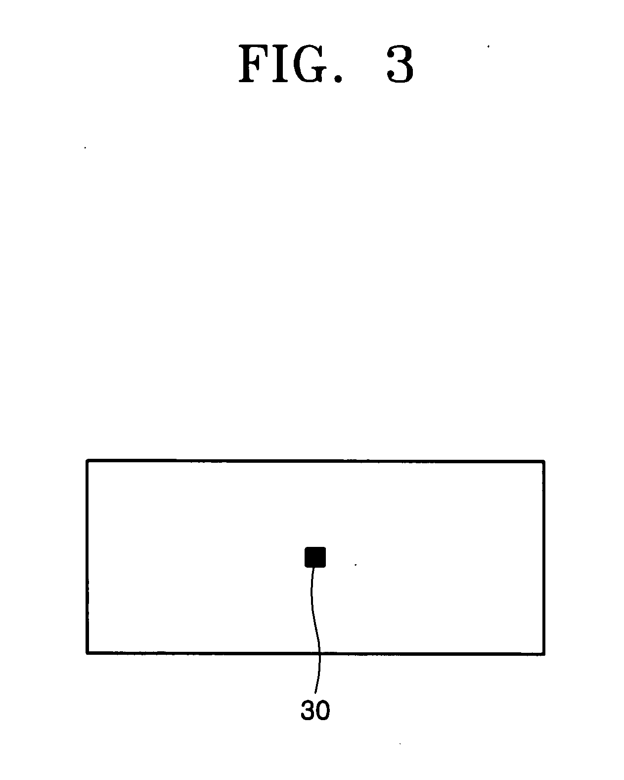
[0027] Referring to FIGS. 1-3, a first waveguide 10 with a low refractive index and a second waveguide 30 with a high refractive index are embedded in a substrate 50. The first waveguide 10 is disposed on a first waveguide region A and, for example, corresponds to an optical fiber with a mode size of 10 μm. The second waveguide 30 is disposed on a second waveguide region C and, for example, has a mode size less than 1 μm. The first and second waveguides 10 and 30 overlap each other on a coupling region B between the first and second waveguide regions A and B.

[0028] Omnidirectional reflectors 20 are disposed on either side of the first waveguide on the first waveguide region A and converge a mode propagating through the first waveguide 10 onto the coupling region B for coupling into the second waveguide 30. In this case, the first waveguide 10 is tapered down in the direction of mode propagation. While the tapering shape is linear as shown in FIG. 1, it may be curved like an exponen...


PUM


Abstract

Provided is a mode converter for use in optical communication. The mode converter includes a first waveguide, a second waveguide optically coupled into the first waveguide, and omnidirectional reflectors that are disposed on either side of the first waveguide and have forward reflectivity with respect to a mode propagating in the first waveguide. The mode converter provides minimum loss coupling between either optical fiber or low index difference waveguide and a high index contrast waveguide. Furthermore, the mode converter achieves high, bi-directional optical coupling over a wide wavelength range with a simple manufacturing process.

Description

BACKGROUND OF THE INVENTION [0001] This application claims priority from Korean Patent Application No. 2003-92508, filed on Dec. 17, 2003, in the Korean Intellectual Property Office, the disclosure of which is incorporated herein in its entirety by reference. [0002] 1. Field of the Invention [0003] The present invention relates to an optical mode converter using omnidirectional reflectors, and more particularly, to an optical mode converter designed to minimize coupling loss through mode conversion between either an optic fiber or a laser diode and a waveguide through which light is transmitted. [0004] 2. Description of the Related Art [0005] In recent years, there has been rapid growth in high-speed Internet access services offered via a communication network such as Asynchronous Digital Subscriber Line (ADSL) or Very-High-Data-Rate DSL (VDSL) by connecting between an Internet Service Provider (ISP)'s sending terminal and a subscriber's terminal via an optic fiber. [0006] An optica...

Claims


Application Information

Patent Timeline
Patent Type & Authority Applications(United States)
IPC IPC(8): G02B6/12G02B6/122G02B6/14
CPCB82Y20/00G02B6/14G02B6/1228G02B6/1225
Inventor KIM, YOUNG-HUNLEE, HONG-SEOKHWANG, SEONG-MONAM, SEUNG-HOKIM, YOUNG-CHAN
Owner SAMSUNG ELECTRONICS CO LTD
Learn More