Chamfering method, forging device used in the chamfering method, and chamfered product

a technology of chamfering and forging, which is applied in the direction of dough shaping, manufacturing tools, applications, etc., can solve the problems of poor available percentage and difficulty in removing weld flash one by one, and achieve the effect of reducing the scattering of the formed chamfer part, maintaining the uniform quality of the product, and improving the steps of work

Inactive Publication Date: 2005-06-23
O OKA CORP
View PDF3 Cites 8 Cited by
  • Summary
  • Abstract
  • Description
  • Claims
  • Application Information

AI Technical Summary

Benefits of technology

[0024] In case of the chamfer part being formed by forging step, the formed chamfer part is accurately uniform to an inch in each product and the scattering of the formed chamfer part is reduced.
[0025] In result, according to the present invention it is possible to improve steps of the work and to maintain the uniform quality of the product.

Problems solved by technology

It was difficult to remove the weld flash one by one.
In result the available percentage was bad.

Method used


Image

  • Chamfering method, forging device used in the chamfering method, and chamfered product
  • Chamfering method, forging device used in the chamfering method, and chamfered product
  • Chamfering method, forging device used in the chamfering method, and chamfered product

Examples


first embodiment

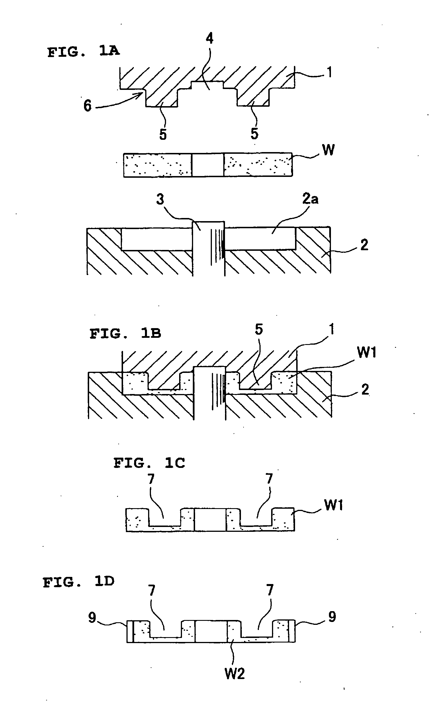
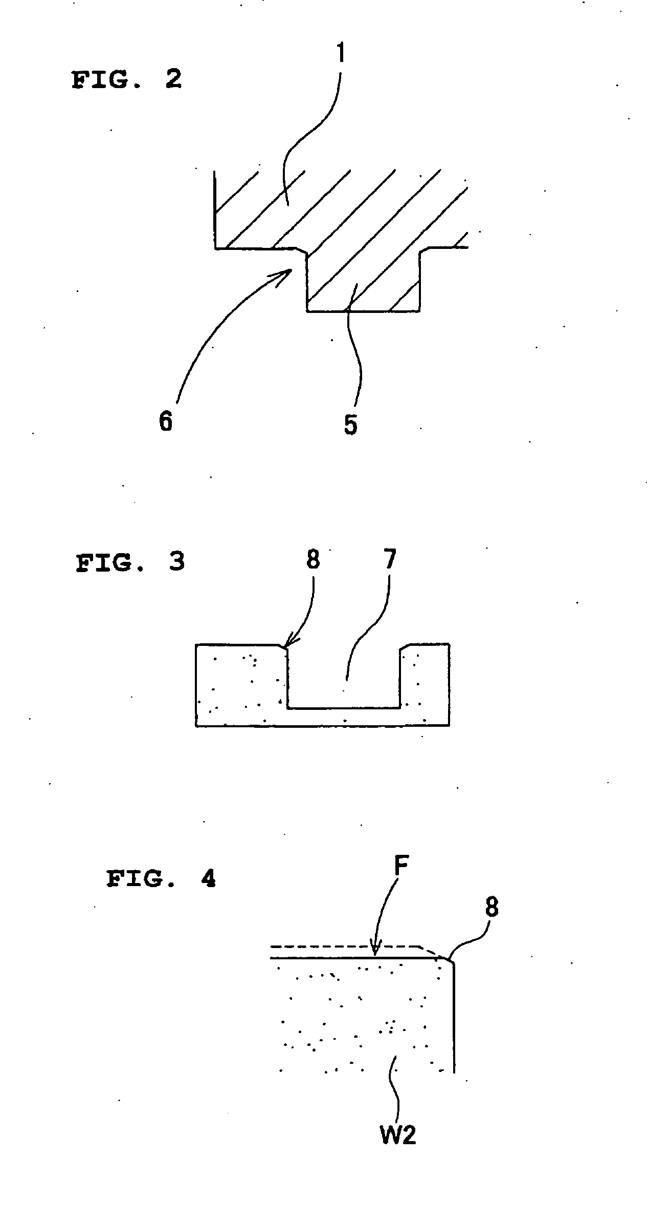
[0050] This forging device have a cope 1 having a punch 10 and a drag 2 having a counter punch 11 and the upper punch 10 and the counter punch 11 are provided symmetrically. Surfaces for forming chamfers 6 are formed around at the bases of these punches 10, 11 corresponding to corner parts of the cut-finished surfaces and the adjacent surfaces as same as the

[0051] Referring to FIG. 6, when a work W is pressed by sending the cope 1 down, the work W is depressed in the cavity 2a and upper and lower concave portions 12, 13 having a chamfer part 8 formed at the corner part of mouth thereof are formed respectively on the surfaces depressed from both sides by the upper punch 10 and the counterpunch 11.

[0052] After removing the work W from the forging device, the both sides surfaces of the work W are finished by cutting.

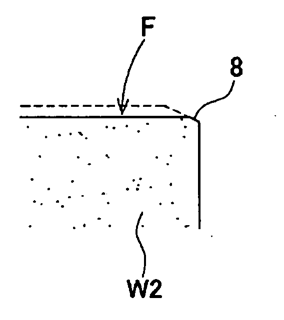
[0053] As described in the first preferred embodiments, the cut-finished surface is cut so as to remain the chamfer part 8 at the corner part of the finished surface F an...

second embodiment

[0059] The top surface of the work W is cut so as to remain a chamfer 8 formed at a corner part of a finished surface F and a penetrating hole 17 as same as the first or second embodiment of the present invention and the bottom surface is cut in the finishing so as to remain the sloping surface 18 and the sloping surface is used in place of the chamfer. And that ends to prevent occurring weld flash.

[0060] The sloping surface of the draft angle is not only used in place of the chamfer, but also as shown in FIG. 8C after molding a penetrating hole, the chamfer may be formed by the sloping surface with the forging device provided a projected down punch 20 having a part for forming 19 on the bottom of a cavity 2a, and then the cut-finished surface will be able to cut by cutting process as shown in FIG. 10.

[0061] In each embodiment, a tooth form is formed by cutting the first molded article having no tooth form. Although, the tooth form, a concave portion and a penetrating hole may be f...


PUM

PropertyMeasurementUnit
angleaaaaaaaaaa
draft angleaaaaaaaaaa
stabilityaaaaaaaaaa

Abstract

A chamfer processing method for forming a chamfer part in a producing method for molding a product which has a cut-finished surface by cutting and penetrated hole or concave portion opening to said cut-finished surface, wherein chamfer processing step for chamfer processing previously the chamfer part by press molding at a corner part between the cut-finished surface and the penetrated hole or concave portion, and cutting step for cut-finishing the cut-finished surface in order to remain the chamfer part on the corner part between the cut-finished surface and the penetrated hole or concave portion.

Description

BACKGROUND OF THE INVENTION [0001] 1. Field of the Invention [0002] The present invention relates to a technology for restraining weld flash generated by cutting process to the minimum when products having a cut-finished surface by cutting and an adjacent surface intersected with the cut-finished surface are molded. [0003] 2. Description of the Related Art [0004] As shown in FIG. 12, a weld flash 22 is generated at a corner part between a cut-finished surface and an adjacent intersecting surface, toward a moving direction of cutting tools, when the cut-finished surface is formed flatly by cutting a part of a molding article. [0005] Therefore a generated weld flash is removed by using a wire brush, a file (rasp) or an electrolytic burring machine, and if necessary, a corner part is chamfered. [0006] In the conventional practice, it was common that one product had many portions whereon weld flash were generated. It was difficult to remove the weld flash one by one. The finished surfac...

Claims


Application Information

Patent Timeline
Patent Type & Authority Applications(United States)
IPC IPC(8): B32B3/02
CPCY10T428/24488B21J5/02
Inventor HOGUCHI, TETSUYA
Owner O OKA CORP
Why Eureka
Try Eureka