Method and device for transferring anisotropic crystal film from donor to receptor, and the donor

a technology of anisotropic crystal films and donor plates, applied in the direction of after-treatment details, polarising elements, instruments, etc., can solve the problems of insufficient sharp edge of coating, inability to reproduce enough to obtain elements of small sizes, and inability to incorporate an additional fabrication process to produce films and parts based on the above films

Active Publication Date: 2005-06-23
NITTO DENKO CORP
View PDF21 Cites 19 Cited by
  • Summary
  • Abstract
  • Description
  • Claims
  • Application Information

AI Technical Summary

Benefits of technology

[0011] The present invention provides a method of fabrication of an anisotropic crystal film on a receptor via transfer from a donor. The present method can maintain the alignment of the surface layer of the anisotropic crystal film transferred from the donor to the receptor.

Problems solved by technology

During fabrication of light, indicatory and other devices, which mainly represents assembly of already prefabricated parts, it is sometimes difficult to incorporate an additional fabrication process to produce films and parts based on the above films.
Additional challenges arise when one needs to fabricate anisotropic coatings with complex configurations or with small pattern features.
This known technique does not require special equipment, however, it does not provide sufficiently sharp edge of the coating and the degree of anisotropy at the edges of the remaining regions, and it is not reproducible enough to obtain elements of small sizes.
Another difficulty is the possible decrease in the degree of crystalline order due to the application of various compressive and shear stresses to the anisotropic crystal film.
However, this method also requires carrying out several additional fabrication operations (installation of an additional fabrication station), and implementation of this method may raise difficulties in selecting suitable chemical agents (suitable composition of the lacquer for polarizing coating, solvent to remove the protective lacquer, etc.).
Difficulties arising in implementation of this method are related firstly to the structure of the transferring polarizing coating and

Method used


Image

  • Method and device for transferring anisotropic crystal film from donor to receptor, and the donor
  • Method and device for transferring anisotropic crystal film from donor to receptor, and the donor
  • Method and device for transferring anisotropic crystal film from donor to receptor, and the donor

Examples


Embodiment Construction

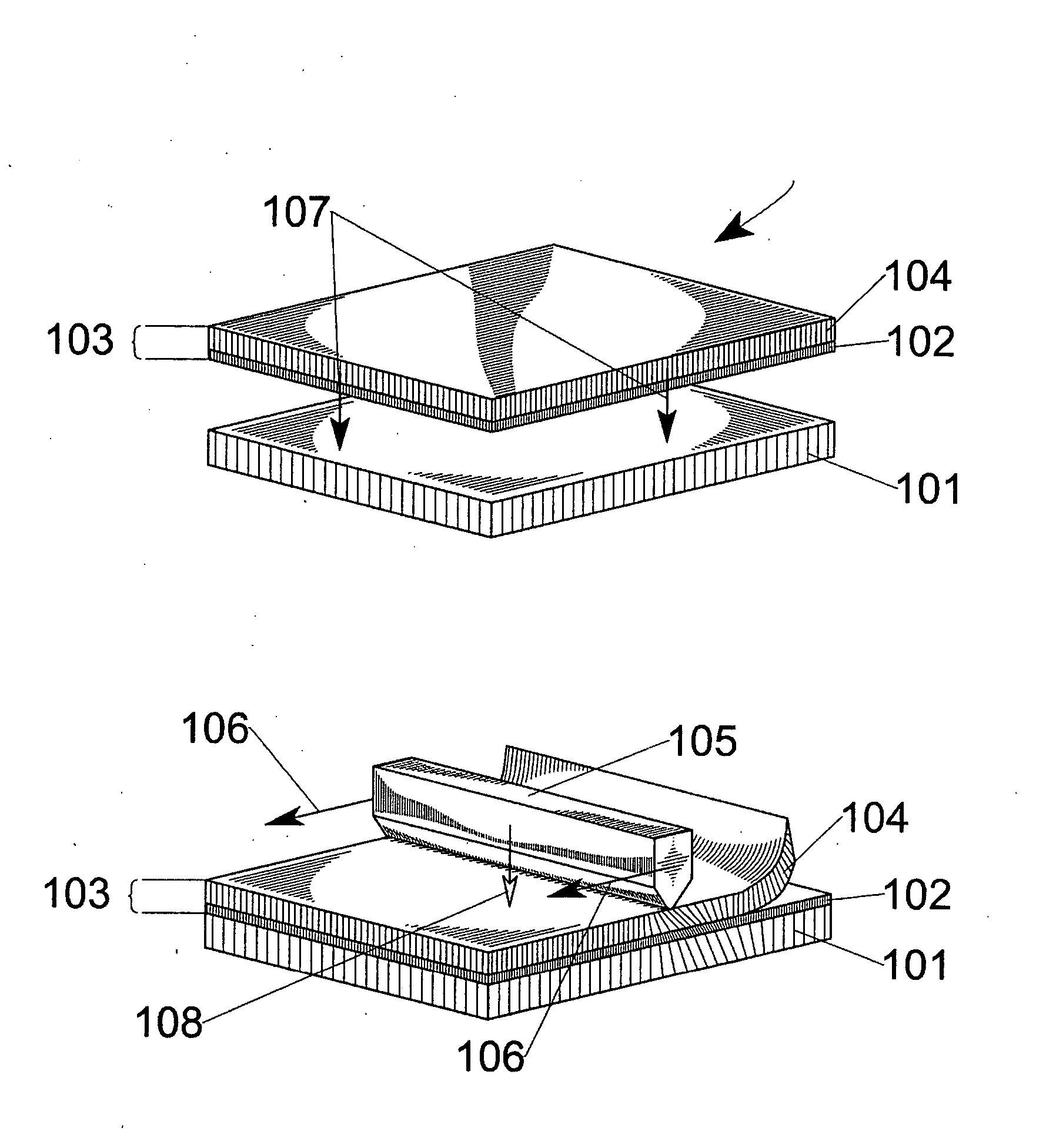
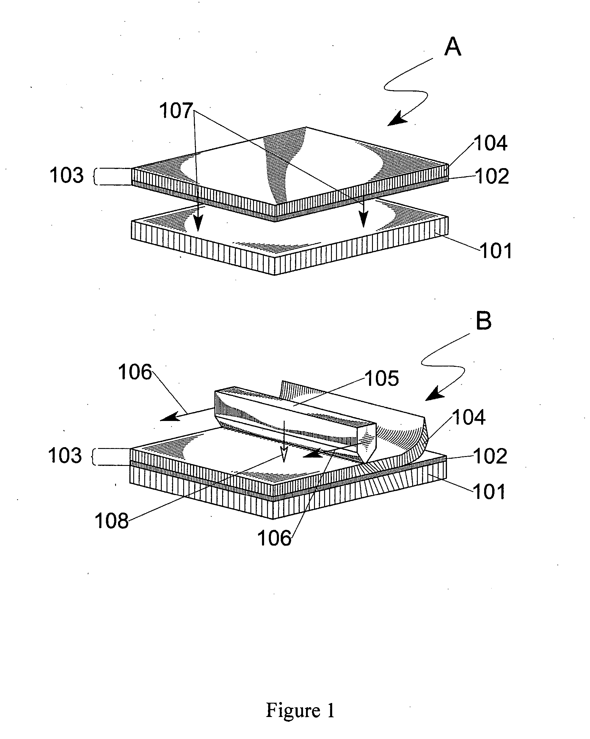
[0032] The present invention provides a method of transferring an anisotropic crystal film from a donor to a receptor. The method is useful in fabricating devices using anisotropic films as polarizers or retarders etc., such as liquid crystal displays (LCDs). The method of the invention is also useful in fabrication of materials and products for automotive industry, architecture, and applied art.

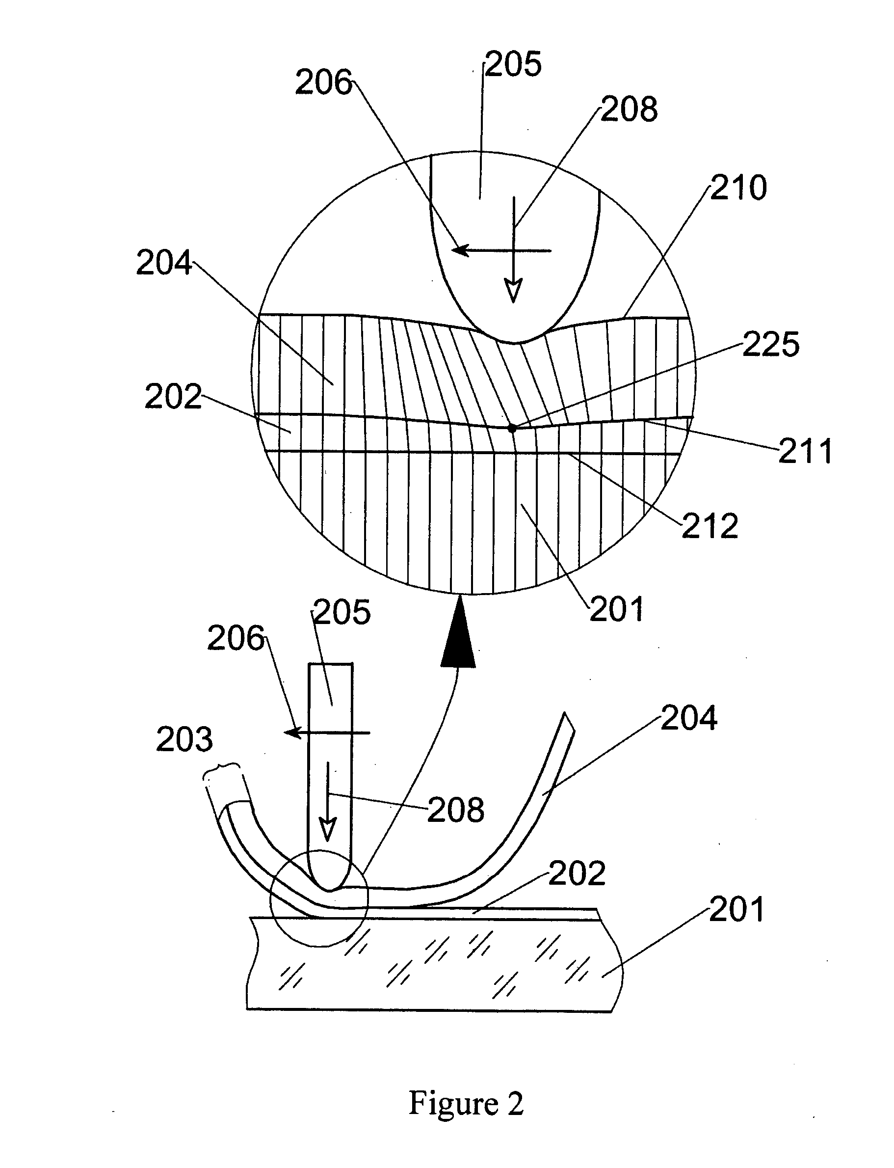
[0033] In general, the method of the invention transfers an anisotropic crystal film from a donor to a receptor. The donor comprises an anisotropic crystal film and a base that serves as a mechanical base for the anisotropic film. A loading is applied to at least a portion of the base to provide shear and compressive stresses onto the base and anisotropic crystal films and the receptor, thereby transferring at least a portion of the anisotropic crystal film onto the receptor. The base is delaminated from the anisotropic crystal film transferred to the receptor. The level of the lording is c...


PUM

PropertyMeasurementUnit
Angleaaaaaaaaaa
Coloraaaaaaaaaa
Structureaaaaaaaaaa

Abstract

A method of forming an anisotropic crystal film, comprising providing a donor which comprises a base and an anisotropic crystal film bounded to the base, and a receptor. At least a portion of the anisotropic crystal film is placed in contact with the receptor. A loading is applied to at least a portion of the base, whereby providing shear and compressive stresses onto the donor and receptor, and transferring at least a portion of the anisotropic crystal film onto the receptor and delaminating the at least portion of the anisotropic crystal film from the base.

Description

FIELD OF THE INVENTION [0001] The invention pertains to the field of fabricating anisotropic films. In particular, the invention relates to methods and devices for transferring anisotropic crystal films from a donor plate to a receptor plate. BACKGROUND OF THE INVENTION [0002] There are known optically anisotropic crystal films, which are obtained from polycyclic organic compounds via special fabrication operations and therefore feature high degree of anisotropy, thermal and light resistance. Technology of fabricating the above films is relatively simple; however it requires special equipment and precise compliance with the fabrication conditions in order to provide reproducibility of parameters of films. During fabrication of light, indicatory and other devices, which mainly represents assembly of already prefabricated parts, it is sometimes difficult to incorporate an additional fabrication process to produce films and parts based on the above films. Additional challenges arise wh...

Claims


Application Information

Patent Timeline
IPC IPC(8): G02B1/02G02B5/30
CPCG02B1/02Y10T156/11Y10S117/915G02B5/3083G02B5/30
Inventor LAZAREV, PAVEL I.PAUKSHTO, MICHAEL V.
Owner NITTO DENKO CORP
Why Eureka
Try Eureka