Fast switching of forward link in wireless system

a wireless system and forward link technology, applied in the field of wireless communication systems, can solve the problems that traditional wireless system architectures and protocols, such as those used in cellular telephone systems, were not designed with the goal of rapid channel change, and achieve the effects of fine time scale, precise and rapid control, and great flexibility in capacity managemen

Inactive Publication Date: 2005-06-23
APPLE INC
View PDF27 Cites 19 Cited by
  • Summary
  • Abstract
  • Description
  • Claims
  • Application Information

AI Technical Summary

Benefits of technology

[0019] Allocation of forward link channels in this fashion affords precise and rapid control over which terminals are assigned to specific traffic channels, on an epoch-by-epoch basis. This arrangement, therefore, affords great flexibility in capacity management, allowing channel allocation decisions to be made on a very fine time scale. For example, channel switch decisions can thus be made rapidly, in response to changes in radio propagation conditions, such as fading conditions.

Problems solved by technology

Unfortunately, users both compete for access to the available radio spectrum, while at the same time demanding data transmission rates that are as fast as possible.
However, traditional wireless system architectures and protocols, such as those used in cellular telephone systems, were not designed with rapid channel changing in mind.

Method used


Image

  • Fast switching of forward link in wireless system
  • Fast switching of forward link in wireless system
  • Fast switching of forward link in wireless system

Examples


Embodiment Construction

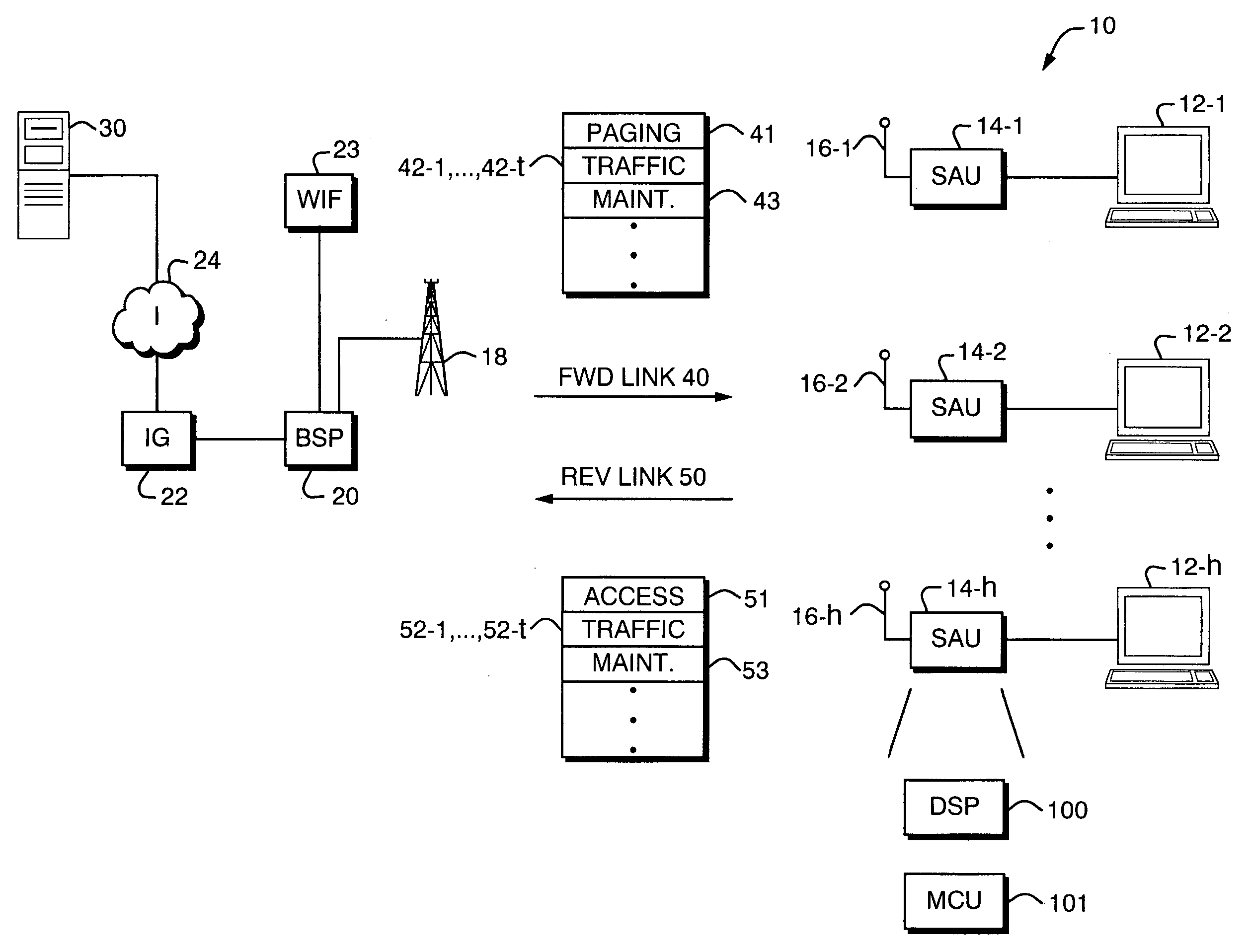
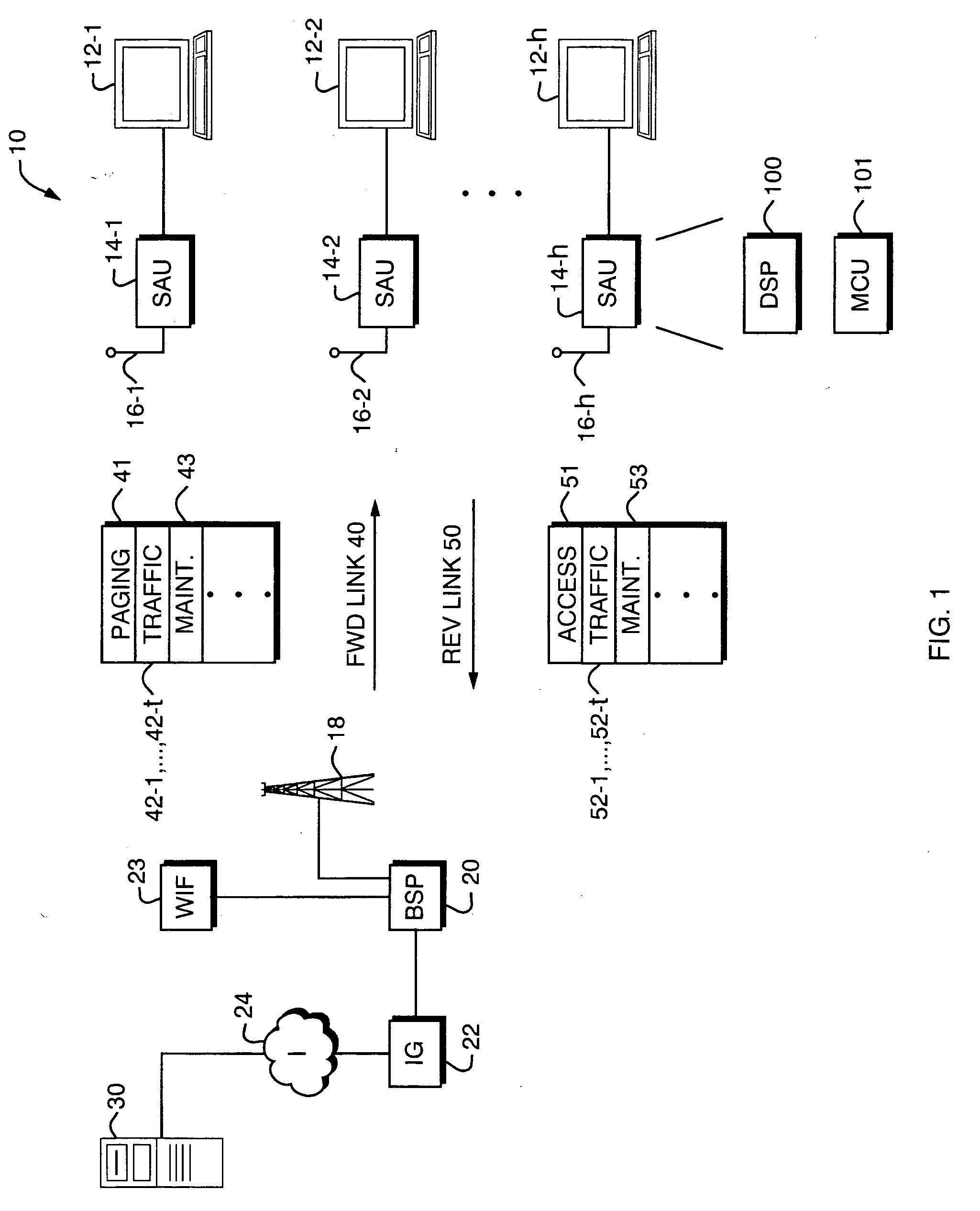
[0027]FIG. 1 is a block diagram of a wireless communication system 10 that makes use of a code channel assignment scheme and message protocol where, prior to the start of each code epoch, a paging channel message is sent that indicates terminal unit identifiers and active channels for such epoch.

[0028] In the following detailed description of a preferred embodiment, the communication system 10 is described such that the shared channel resource is a wireless or radio channel. However, it should be understood that the techniques described here can be applied to allow shared access to other types of media such as telephone connections, computer network connections, cable connections, and other physical media to which access is granted on a demand driven basis.

[0029] The communication system 10 includes a number of Personal Computer (PC) devices 12-1, 12-2, . . . 12-h, . . . 12-1, corresponding remote, mobile Subscriber Access Units (SAUs) 14-1, 14-2, . . . 14-h, . . . 14-1, and assoc...


PUM


Abstract

A technique for distributing channel allocation information in a demand access communication system. In a preferred embodiment, for use with Code Division Multiple Access (CDMA) type communication, multiple access codes are used that have a defined code repeat period or code epoch. For each such epoch duration, a central controller, such as located at a base station in the case of operating a forward link, determines a schedule of assignment of traffic channels to active terminals for each epoch. For each terminal designated as active during the epoch, an active terminal unit identifier is assigned. For each terminal designated as active during the epoch, the base station assigns a list of active channels for such terminal unit. Prior to the start of each epoch, a channel set up message is sent on one of the forward link channels, such as a paging channel. The channel set up message indicates the terminal unit identifiers and the lists of active channels for epochs of the associated traffic channel(s) that are to follow. At the remote terminal unit, upon receiving a paging channel message, an active terminal identifier is determined from each paging channel message and compared to a previously assigned terminal identifier. On a predetermined subsequent epoch, the indicated active traffic channel, as indicated from the list of active traffic channels indicated by a received paging channel message, are then processed.

Description

RELATED APPLICATION [0001] This application is a continuation of U.S. application Ser. No. 09 / 847,860, filed May 2, 2001. The entire teachings of the above application are incorporated herein by reference.BACKGROUND OF THE INVENTION [0002] This invention relates generally to wireless communication systems, and more particularly to a technique for high speed re-allocation of coded radio channel resources that are shared among a number of users. [0003] Demand for wireless communications equipment and services continues to grow at an unprecedented rates throughout the world. Increasingly, such systems are commonly relied upon to provide voice and data communications to a growing sector of the public. While these systems originally depended upon analog signaling technology, there is essentially unanimous agreement that future systems will be based on various types of digital signal coding schemes. [0004] The typical wireless communication system is a point to multi-point type system in ...

Claims


Application Information

Patent Timeline
Patent Type & Authority Applications(United States)
IPC IPC(8): H04B7/26H04L12/56H04W8/26H04W68/00H04W72/04H04W72/12H04W74/00H04W76/02
CPCH04B7/2628H04W8/26H04W68/00H04W72/0446H04W72/12H04W76/02H04W72/042H04W76/10H04W72/23
Inventor ALAPURANEN, PERTTI OLAVIJOHNSON, KEVIN P.FARLEY, KEVIN L.
Owner APPLE INC
Why Eureka
Try Eureka