

Oven or grill burner, venturi tube, mounting for a thermocouple and/or an igniter, and process for fabricating said burner
a technology for ovens and grills, which is applied in the field of ovens or grill burners, can solve the problems of high steel cost, low efficiency of fire and thus heat distribution, and leakage of closing parts, and achieves the effects of preventing the rotation of mountings, simple and inexpensive means, and great functional and construction adaptability
- Summary
- Abstract
- Description
- Claims
- Application Information
AI Technical Summary
Benefits of technology
Problems solved by technology
Method used
Image

Examples
first embodiment
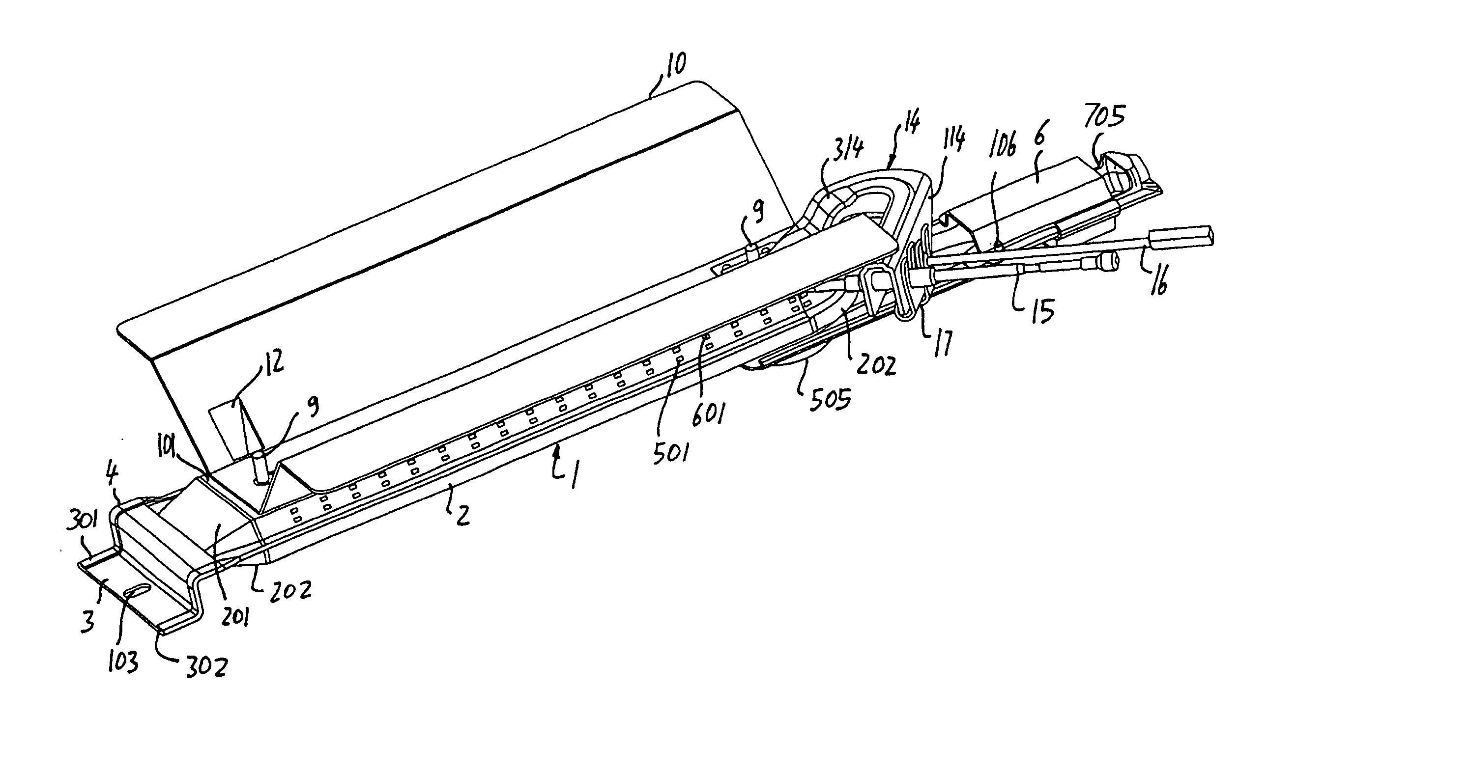
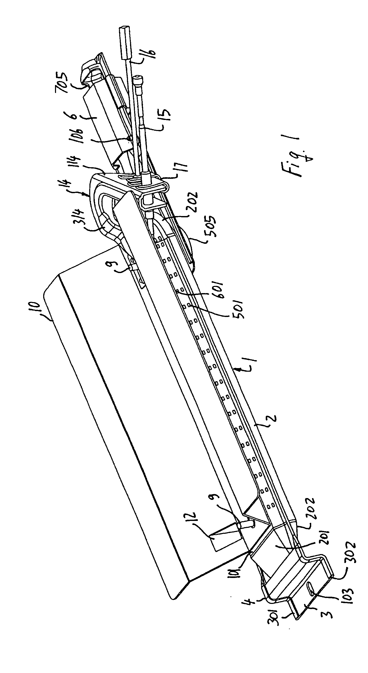
[0075] Referring to FIGS. 1 to 4, a burner according to this invention first includes a pair of half shells, an upper half shell 1 and a lower half shell 2. In this regard, it shall be noted that the words upper and lower are used herein in relation to a burner fitted inside the oven on the bottom wall or immediately beneath the top wall (grill or broiler). The two half shells 1, 2 are elongated and respectively have an upper face 101 and a lower face 102 that are substantially flat and form, in the coupled condition, a tubular body which also has an elongated but substantially flat shape, and integrates, even in the exterior aspect, the two typical characteristics of tubular and flat burners respectively. Two corresponding ends 201, 202 of the upper half shell 1 and of the lower half shell 2 are conformed in such a manner that, when the two half shells 1, 2 are joined together, they automatically form a flame arc forming head. The opposite corresponding ends 301, 302 of the shells ...
second embodiment
[0079] Referring now to FIGS. 5 to 12, a burner according to this invention is shown. This burner is composed of two half shells, an upper half shell 18 and a lower half shell 19, each including the upper half shell and the lower half shell of the venturi tube respectively. Therefore, in this case the half shells of the venturi tube are made of one piece as axial extensions of the half shells 18, 19 which form the tubular burner body, whereby, in the assembled condition, the venturi tube is coaxial to the tubular burner body. The two half shells 18, 19 are elongated and respectively have an upper face 218 and a lower face 219 that are substantially flat and form, in the joined condition, a tubular body which also has an elongated but substantially flat shape. The junction plane between the two half shells 18, 19 is substantially parallel both to the bottom and / or the top of the oven and to the outer faces 218, 219 of the two half shells 18, 19, the latter being therefore parallel. T...
third embodiment
[0086] Referring now to FIG. 13, the burner of this invention is shown, in which both opposite ends of the tubular body of the burner are truncated and the venturi tube 27 is provided as a separate body, to be secured onto one of these ends, by using a method like the one described above for the flame arc forming head 21. The opposite end is closed by a flame arc forming head 21, which may have the same characteristics as described above. Alternatively, the venturi tube 27 may be connected to the tubular body 26 of the burner through a tubular joint, particularly made of a die cast material, which may be rectilinear 28 or curved 29. In the first case, the venturi tube 27 is aligned with the tubular body 26, whereas in the second case it extends transverse thereto.
PUM
| Property | Measurement | Unit |
|---|---|---|
| angle | aaaaa | aaaaa |
| angle | aaaaa | aaaaa |
| shape | aaaaa | aaaaa |
Abstract
Description
Claims
Application Information