Efficient control for smoothly and rapidly starting up an absorption solution system

Inactive Publication Date: 2005-06-30
CARRIER CORP
View PDF3 Cites 8 Cited by
  • Summary
  • Abstract
  • Description
  • Claims
  • Application Information

AI Technical Summary

Benefits of technology

[0009] In a disclosed embodiment of this invention, system feedback is utilized to control the amount of heat delivered into the generator for an absorption chiller at start-up. In a preferred embodiment, the feedback is taken from the temperature

Problems solved by technology

If the heat is directed into the chiller immediately, there is undesirable vibration, and noise, due to vapor being mixed with solution in the heat exchanger pipes, and rapid thermal expansion.
These effects can reduce product life and also cause undesirable noise.
The example above is for startup conditions but those skilled in the art would appreciate that a similar problem could occur under any conditions where a large change in s

Method used


Image

  • Efficient control for smoothly and rapidly starting up an absorption solution system
  • Efficient control for smoothly and rapidly starting up an absorption solution system
  • Efficient control for smoothly and rapidly starting up an absorption solution system

Examples


Embodiment Construction

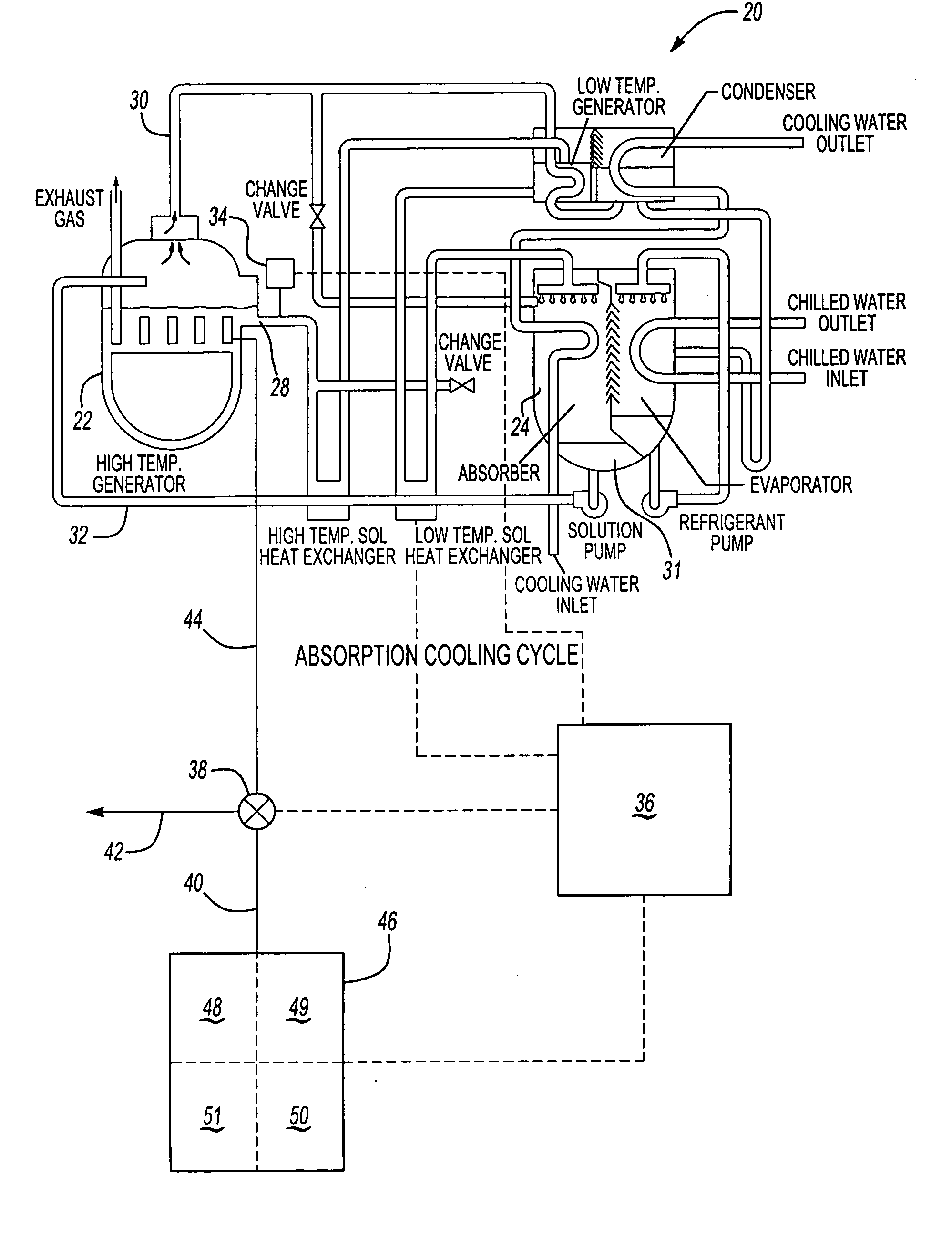
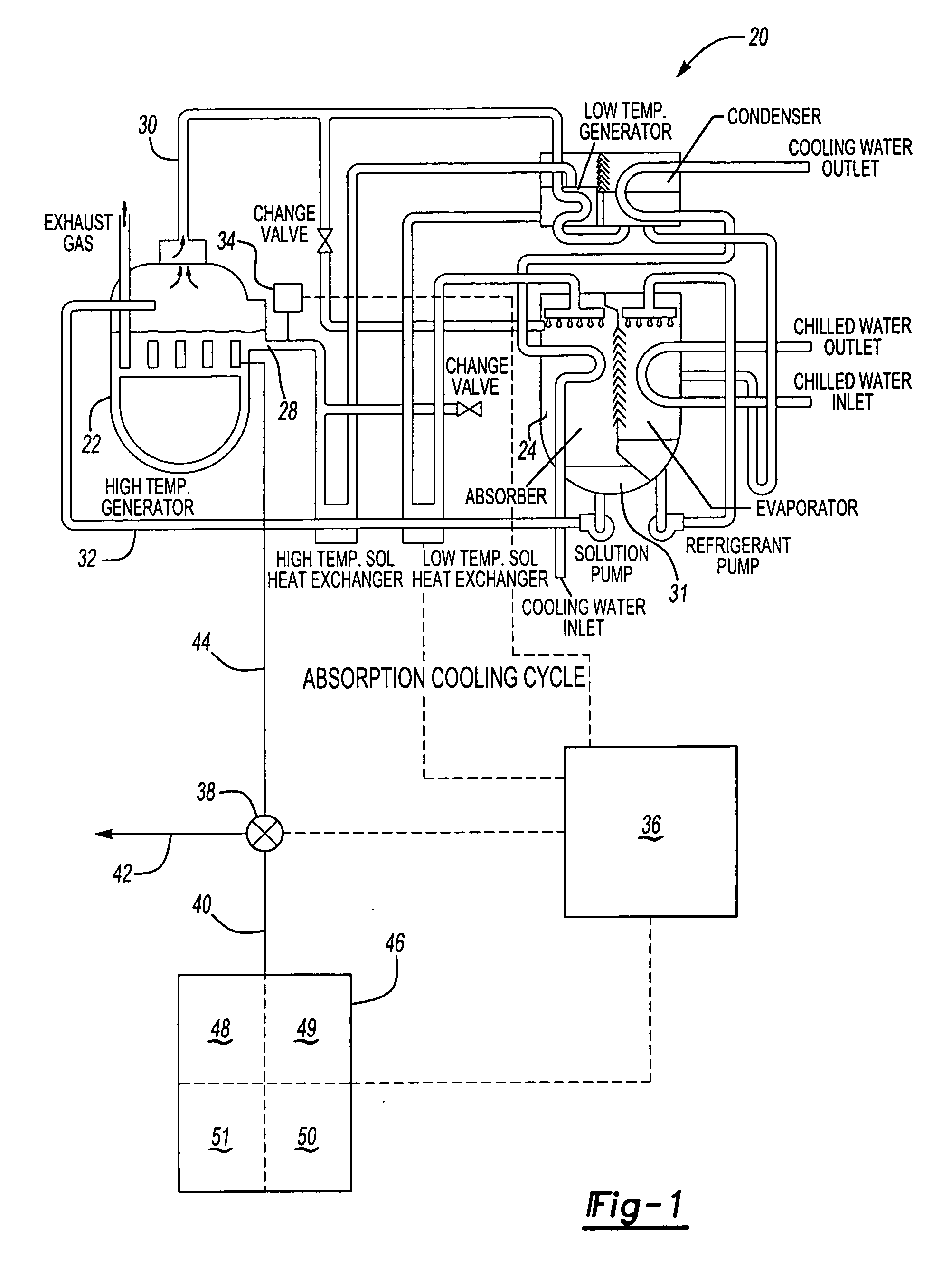
[0020] An absorption chiller system 20 is illustrated in FIG. 1. As shown, an evaporator 24 receives flow from a refrigerant line 30. Refrigerant in line 30 is delivered through an outlet to drip or fall on a water tube. In the event that the system 20 is a chiller, the tube will carry water that is to be cooled, and then utilized to cool environmental air in a building. Alternatively, as mentioned above, the water could be heated, with the refrigerant leaving the outlet being a heated refrigerant. Again, the details of the change to provide this function are within the skill of a worker in this art.

[0021] A second line 28 delivers an absorption solution into the absorber, positioned next to the evaporator 24. Ultimately, a mixture of the refrigerant and absorption solution, or diluted LiBr solution, gathers at 31, and is returned through a line 32 to a generator 22. A source of heat is delivered through a line 44 into the generator 22. This source of heat boils refrigerant out of ...


PUM


Abstract

An absorption chiller system has an efficient start-up control that monitors system condition, and in particular the absorption solution temperature. The system limits the amount of heat delivered into the absorption chiller generator, to provide a gradual rise in the absorption solution temperature at start-up. In this manner, undesirable noise vibration and rapid thermal expansion, which may have occurred in the past is reduced or eliminated.

Description

BACKGROUND OF THE INVENTION [0001] This invention relates to a control that utilizes the absorption solution temperature as feedback for controlling the amount of heat delivered into an absorption chiller at start-up. [0002] Absorption solution / refrigerant systems are utilized in many applications to provide chilled or heated water for environmental control in buildings, etc. In a basic system, an absorber separately receives a flow of an absorption solution (concentrated LiBr), and a refrigerant. The refrigerant is often water. The refrigerant is directed onto a tube, which would carry water to be chilled for part of a building air conditioning system. The absorption solution is also directed into the absorber and is cooled. Within the absorber, the absorption solution and the liquid refrigerant combine. The absorption solution, at this point, is at the proper temperature and concentration that enables it to absorb the refrigerant vapor. It will then carry this refrigerant with it ...

Claims


Application Information

Patent Timeline
IPC IPC(8): F25B15/00F25B15/06F25B27/02F25B49/04
CPCF25B15/008F25B15/06F25B2500/26F25B49/043F25B27/02Y02A30/274
Inventor HALWAN, VIVEKMARLER, MARK E.
Owner CARRIER CORP
Why Eureka
Try Eureka