
Magnesium die casting system

a magnesium die casting and magnesium alloy technology, applied in the field of magnesium die casting systems, can solve the problems of reducing the production efficiency of magnesium alloy casting, and reducing so as to reduce the operating cost of the system, prevent the exposure of re-melted materials, and reduce the amount of cover gas needed

Inactive Publication Date: 2005-06-30
BOULET ALAIN RENAUD
View PDF7 Cites 2 Cited by
  • Summary
  • Abstract
  • Description
  • Claims
  • Application Information

AI Technical Summary

Benefits of technology

[0017] The shot sleeve may be filled from the underside through an underflow filling tube. Filling from the underside provides laminar filling characteristics and prevents splashing within the shot sleeve. Filling the shot sleeve from the underside also causes the molten metal to push gases out of the shot sleeve as it is being filled, preventing entrapment of gases which can lead to casting porosity and poor part quality.
[0033] Due to the high temperatures involved, automation of part removal and scrap trimming processes using a robot or similar means may be used. The robot may then quench the cast part only, not the runner system, and place the casting in a trim press without releasing the runner. Once the part is trimmed, the robot adds the runner to the re-melt furnace for recycling. Since the runner system being fed into the re-melt furnace is already hot, there is a resulting energy savings when an in-line recycling system is used. Automation reduces the likelihood of contamination of the scrap portion of the casting due to reduced handling. An air-lock may be used to introduce scrap magnesium to prevent the introduction of air and / or contaminants to the re-melt furnace that may affect cover gas purity. The air-lock may have a lid that opens in a clam-like fashion. The air-lock may be referred to as a clam-shell.

Problems solved by technology

Although magnesium has a higher strength to weight ratio than aluminum, castings made from magnesium typically suffer from porosity, which compromises casting strength.
As a result, many dies are currently designed to produce castings with features such as thicker ribs and wall sections, thus eliminating weight savings realized through the use of magnesium and making the finished part unacceptably high in cost.
These techniques generally are unsuitable when applied to magnesium die casting.
Filling the shot sleeve using a vacuum is difficult with magnesium because of the much higher filling temperature as compared with aluminum.
The high temperature makes it difficult to maintain a vacuum seal and lead to excessive equipment maintenance.
Also, since the cycle time between each shot sleeve filling operation is quite long, in excess of ten seconds, and since magnesium cools at a rate approximately three times faster than aluminum, the magnesium has a tendency to solidify within the shot sleeve and runners.
Solidification prevents rapid pressure intensification, leading to poor part quality and large numbers of scrap castings.
The long cycle times also do not permit economically acceptable production rates.
The manner in which the shot sleeve is filled also affects the quality of magnesium die castings.
Improper filling of the shot sleeve can cause non-uniform metal flow, entrapment of gases that cause casting porosity, and segregation of impurities, such as magnesium oxide.
These factors detrimentally affect the quality of the castings produced.
However, vacuum methods commonly used with aluminum cannot be readily applied to magnesium.
This can largely be attributed to the extensive runner system required to completely fill the die, which becomes scrap once the part is cast.
It is expensive to have magnesium recycled in this manner due to recycling costs, increased inventory requirements, and handling costs.
However, during globule formation, liquid metal is entrapped within the globules, resulting in a loss of recyclable material.
The withdrawal and addition of fresh material can lead to temperature fluctuations within the furnace and increased crucible maintenance.
Also, flux cannot be introduced into the die castings and flux based processes are typically conducted off-line to minimize the risk of casting contamination.
The cooling and re-heating of the scrap material consumes a great deal of energy, making off-line flux based recycling processes expensive and impractical.

Method used


Image

  • Magnesium die casting system
  • Magnesium die casting system
  • Magnesium die casting system

Examples


Embodiment Construction

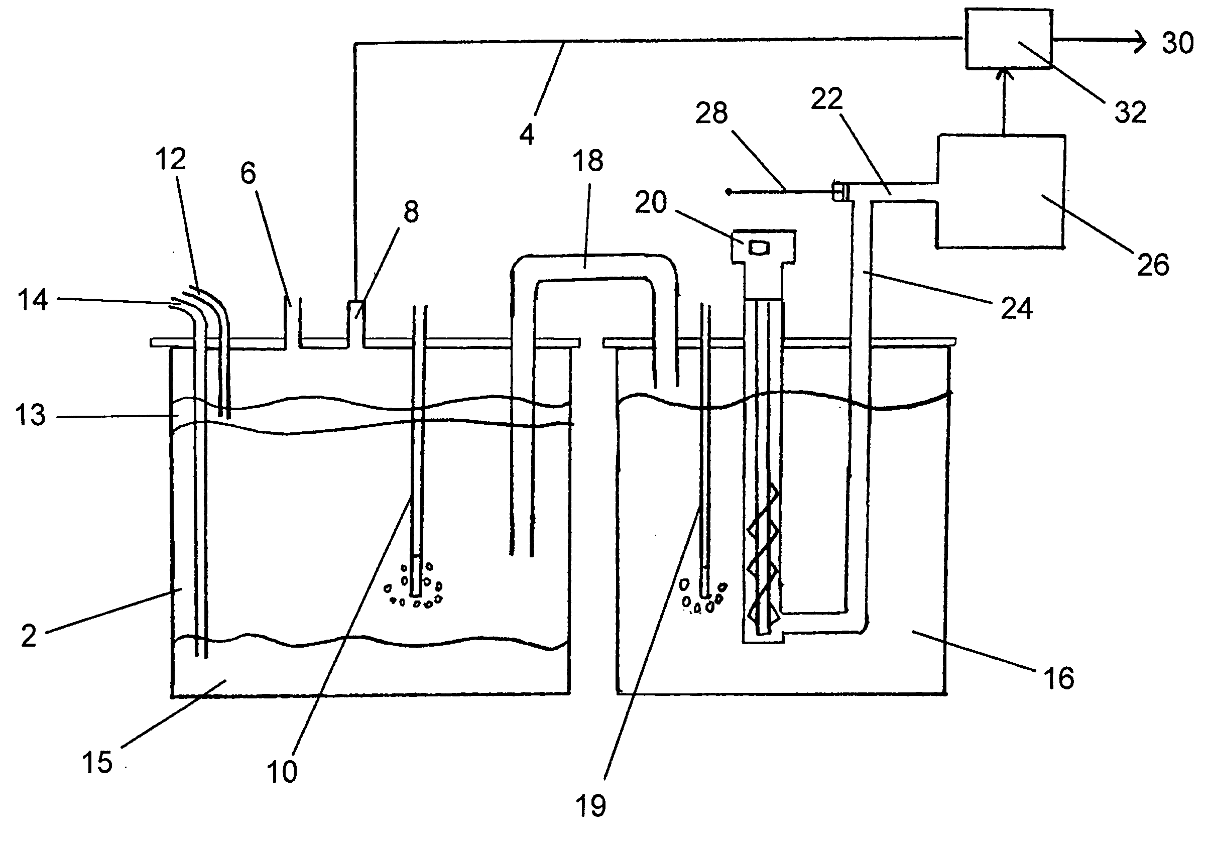
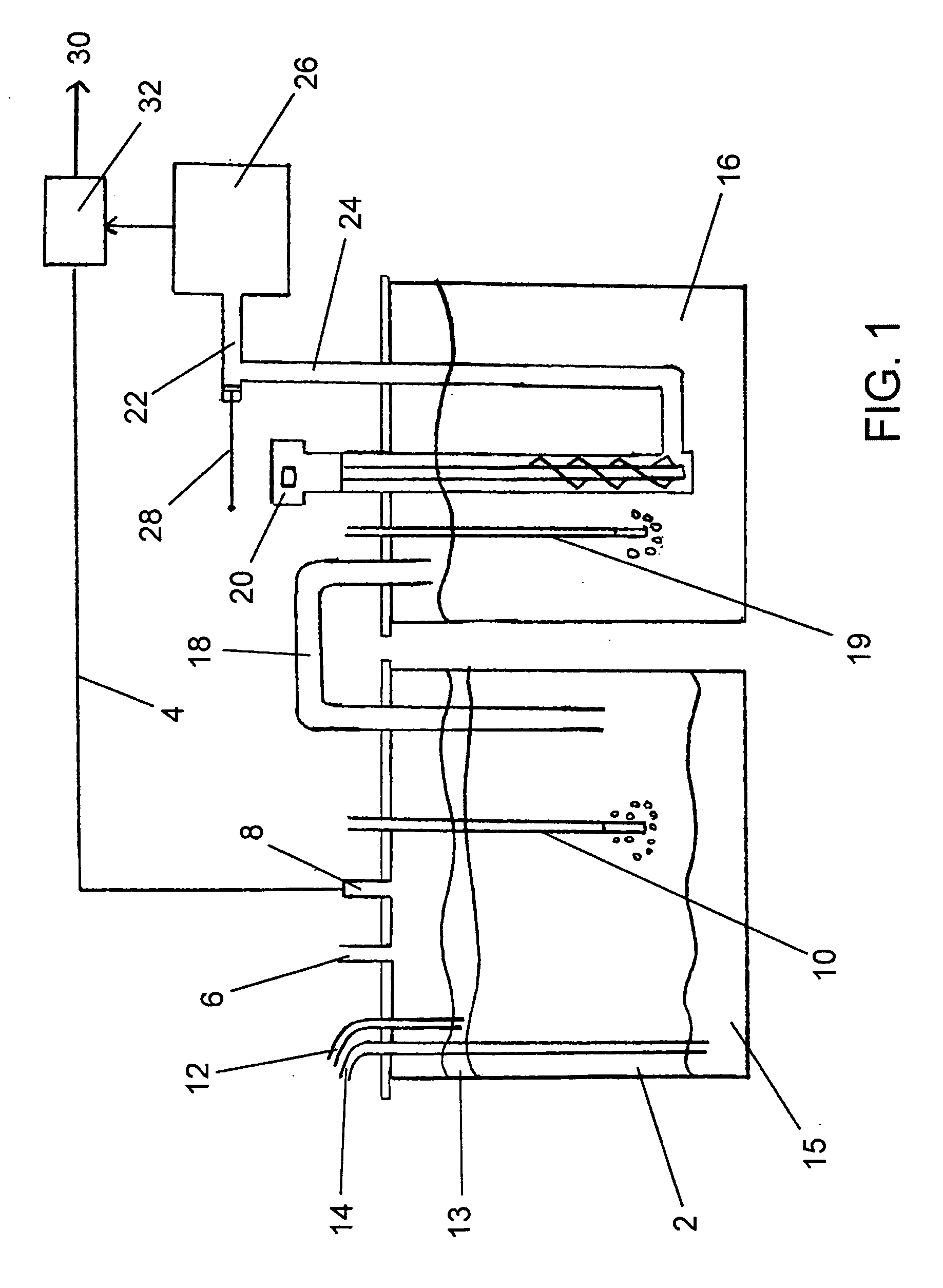
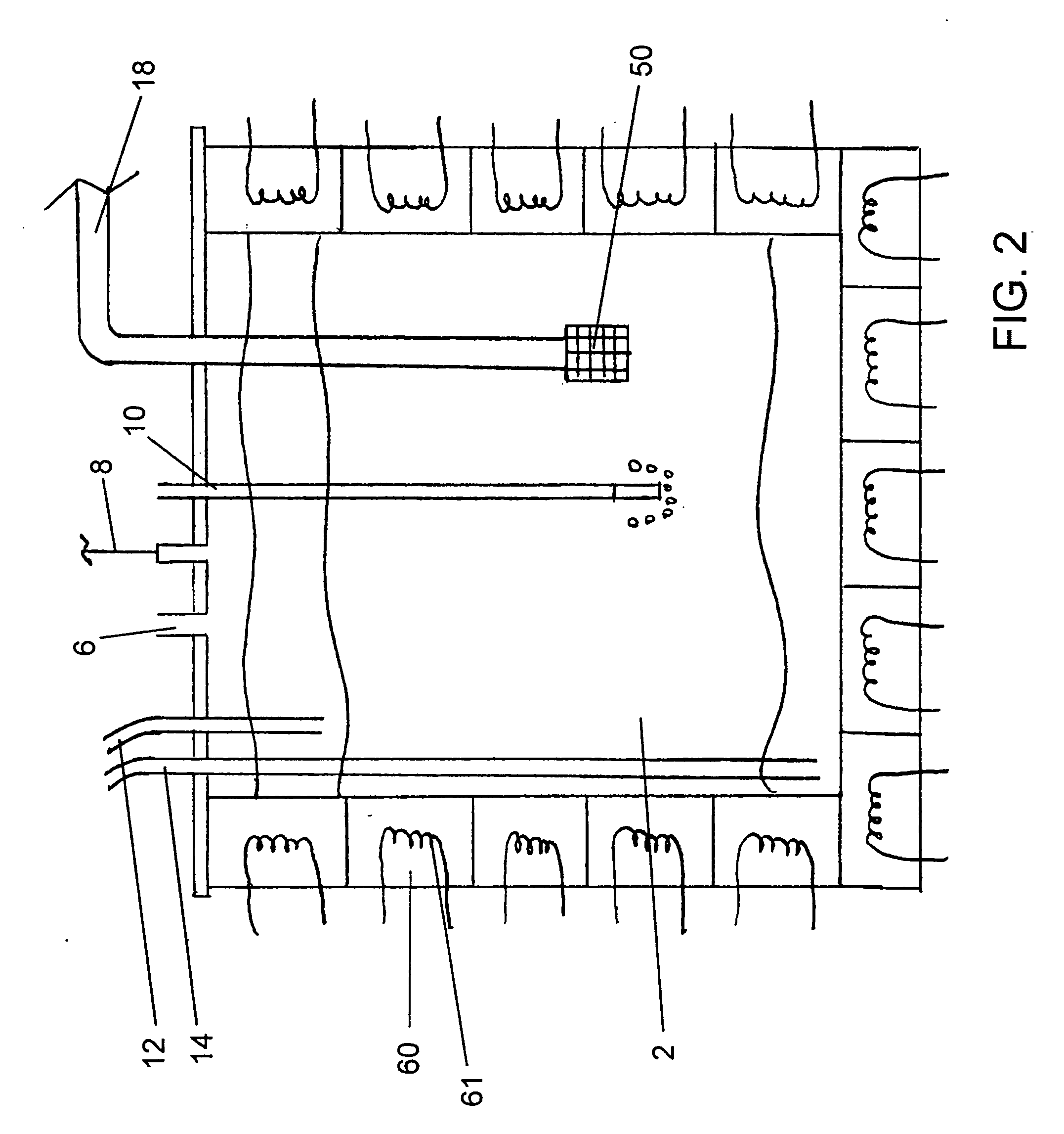
[0037] With reference to FIG. 1 the in-line re-melt system is described. The re-melt furnace has a scrap opening 8 for feeding of scrap material by the robot. A virgin opening 6 is also provided to allow feeding of pre-heated virgin magnesium material for mixing with the re-cycled material. Both feeding operations are performed without introducing contaminants, such as gases, that might adversely affect the metal purity. Sparging with inert gases is performed using a sparger 10 situated within the furnace. Impurities are stratified within the re-melt furnace to create at least three regions. Light weight impurities, such as oxides, float to the top region 13. Heavy impurities, such as sludge, sink to the bottom region 15. A clean region 2 is maintained between the top and bottom regions. The stratified impurities are withdrawn from the top region 13 using top withdrawal tube 12 and from the bottom region 15 using bottom withdrawal tube 14. Impurities are withdrawn in either a contin...


PUM

PropertyMeasurementUnit
cycle timeaaaaaaaaaa
timeaaaaaaaaaa
cycle timeaaaaaaaaaa

Abstract

An improved magnesium die casting system incorporates filling of the shot sleeve from the underside and / or in-line re-melting of scrap magnesium using a re-melt furnace. A pump is used to transfer molten magnesium from a casting furnace to the shot sleeve through an underflow filling tube. The shot sleeve is filled in a laminar manner, minimizing entrapped gases. The in-line re-melt system allows recycling of scrap in-house and reduces energy cost associated with heating and re-heating scrap. The improved system increases casting quality and reduces scrap rates and recycling costs.

Description

CROSS-REFERENCE TO RELATED APPLICATIONS [0001] This application is a divisional of U.S. patent application Ser. No. 10 / 706,273, filed Nov. 13, 2003, which claims the benefit of U.S. Patent application 60 / 425,630, filed Nov. 13, 2002, both of which are hereby incorporated herein by reference.FIELD OF THE INVENTION [0002] The invention relates to an improved system for magnesium die casting. More specifically, the invention relates to an improved system for supplying molten magnesium to a die casting machine and / or for supplying recycled scrap magnesium to a die casting machine. BACKGROUND OF THE INVENTION [0003] Magnesium alloys are a strong and light weight alternative to traditional alloys, such as aluminum alloys. Although magnesium has a higher strength to weight ratio than aluminum, castings made from magnesium typically suffer from porosity, which compromises casting strength. As a result, many dies are currently designed to produce castings with features such as thicker ribs a...

Claims


Application Information

Patent Timeline
Patent Type & Authority Applications(United States)
IPC IPC(8): B22D17/30B22D21/04
CPCB22D17/30
Inventor BOULET, ALAIN RENAUD
Owner BOULET ALAIN RENAUD
Learn More