Vibration proofing heat shield plate

a heat shield plate and vibration-proof technology, applied in the direction of shock absorbers, machines/engines, machine supports, etc., can solve the problems of wire mesh member damage and noise generation, and achieve the effect of high heat shielding

Active Publication Date: 2005-06-30
NICHIAS CORP +1
View PDF17 Cites 20 Cited by
  • Summary
  • Abstract
  • Description
  • Claims
  • Application Information

AI Technical Summary

Benefits of technology

[0004] However, in the heat shield plate having the high heat shielding effect as mentioned above, the collar member and the wire mesh member come into collision with each other due to a lateral vibration of the exhaust manifold, whereby there are generated problems that a noise is generated and the wire mesh member is damaged.

Problems solved by technology

However, in the heat shield plate having the high heat shielding effect as mentioned above, the collar member and the wire mesh member come into collision with each other due to a lateral vibration of the exhaust manifold, whereby there are generated problems that a noise is generated and the wire mesh member is damaged.

Method used


Image

  • Vibration proofing heat shield plate
  • Vibration proofing heat shield plate
  • Vibration proofing heat shield plate

Examples


Embodiment Construction

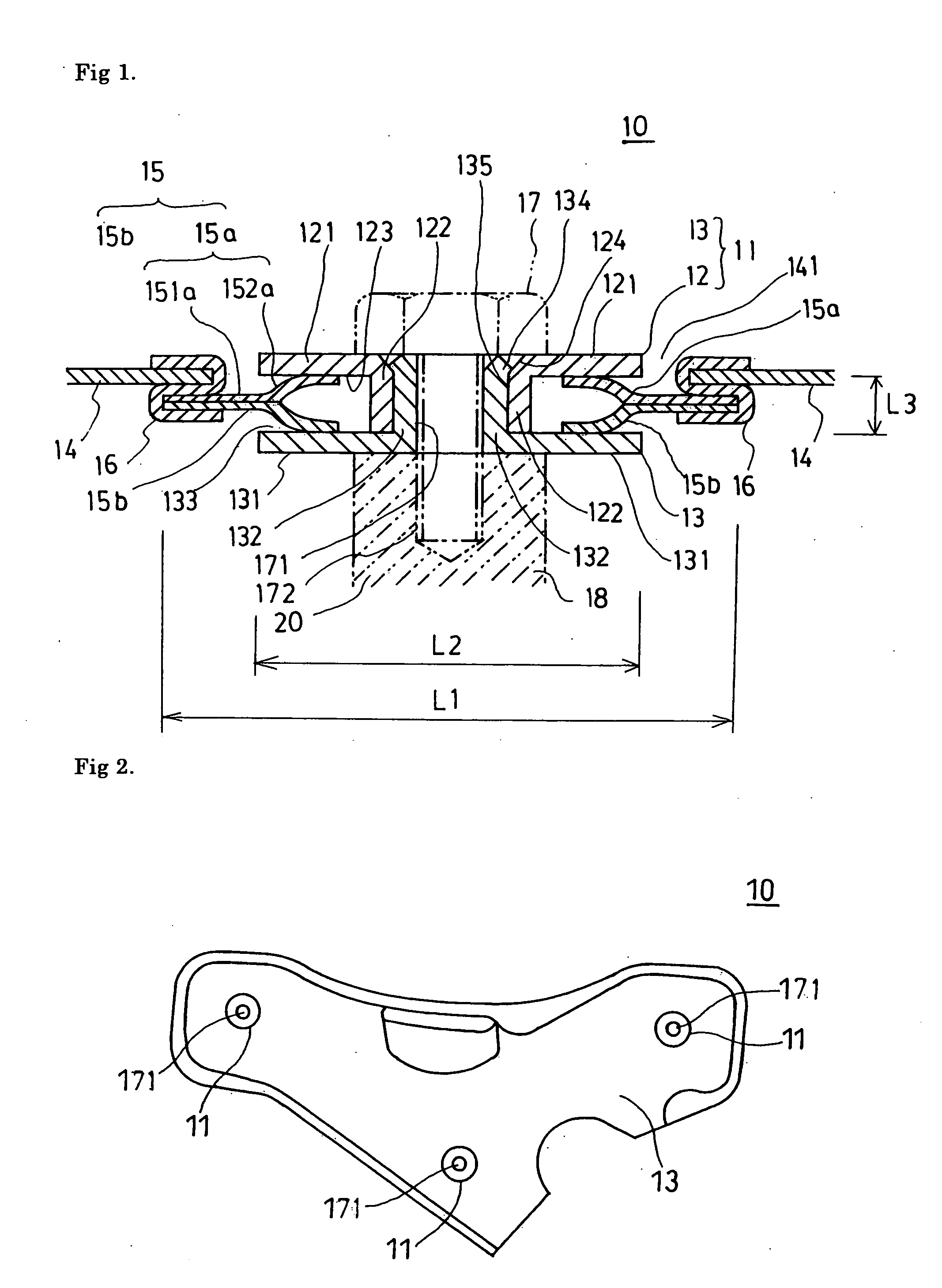
[0015] Next, a description will be given of a vibration proofing heat shield plate of an embodiment of the present invention with reference to FIGS. 1 and 2. In this case, in the present specification, upper and lower mean upper and lower in the drawings for convenience of explanation.

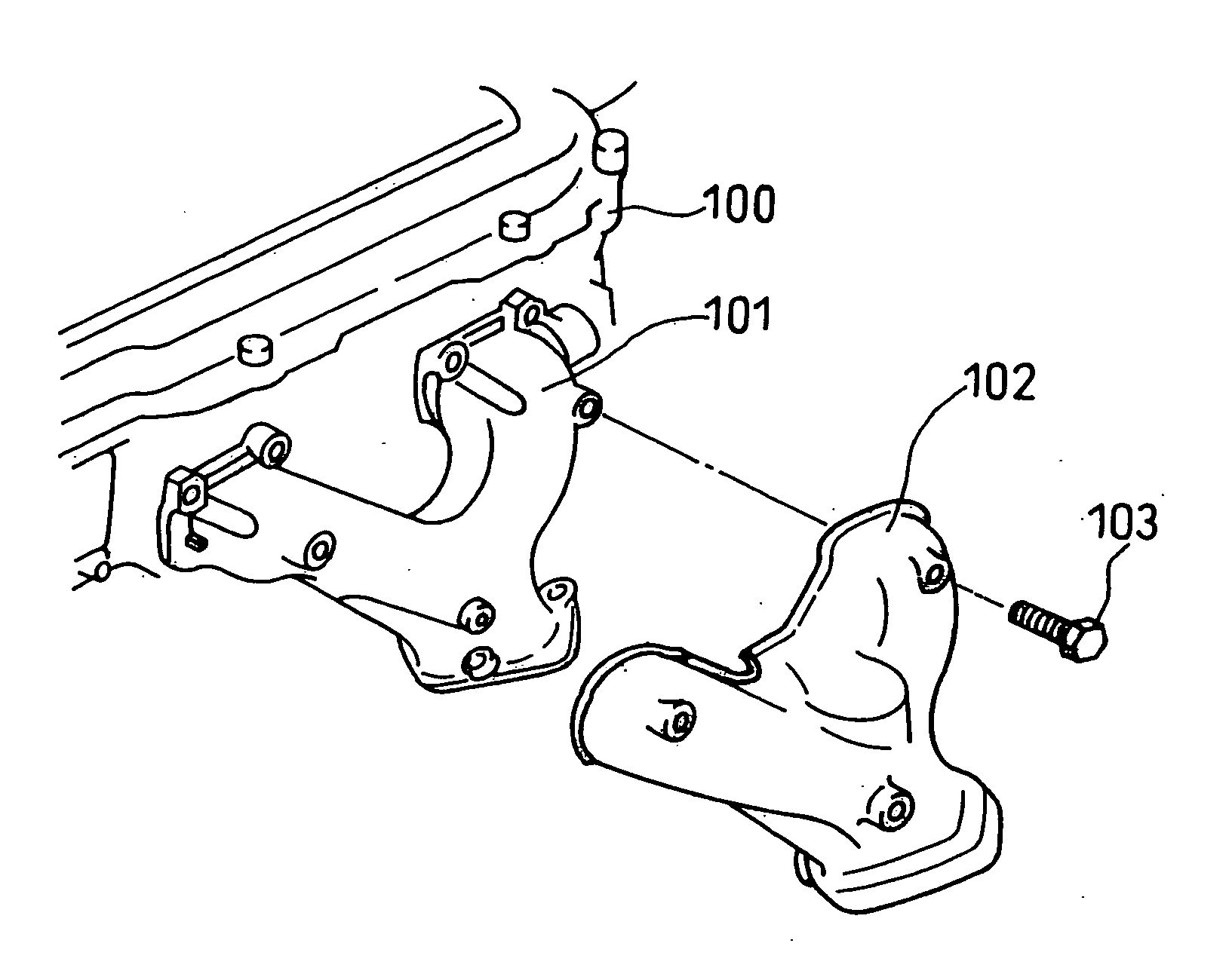
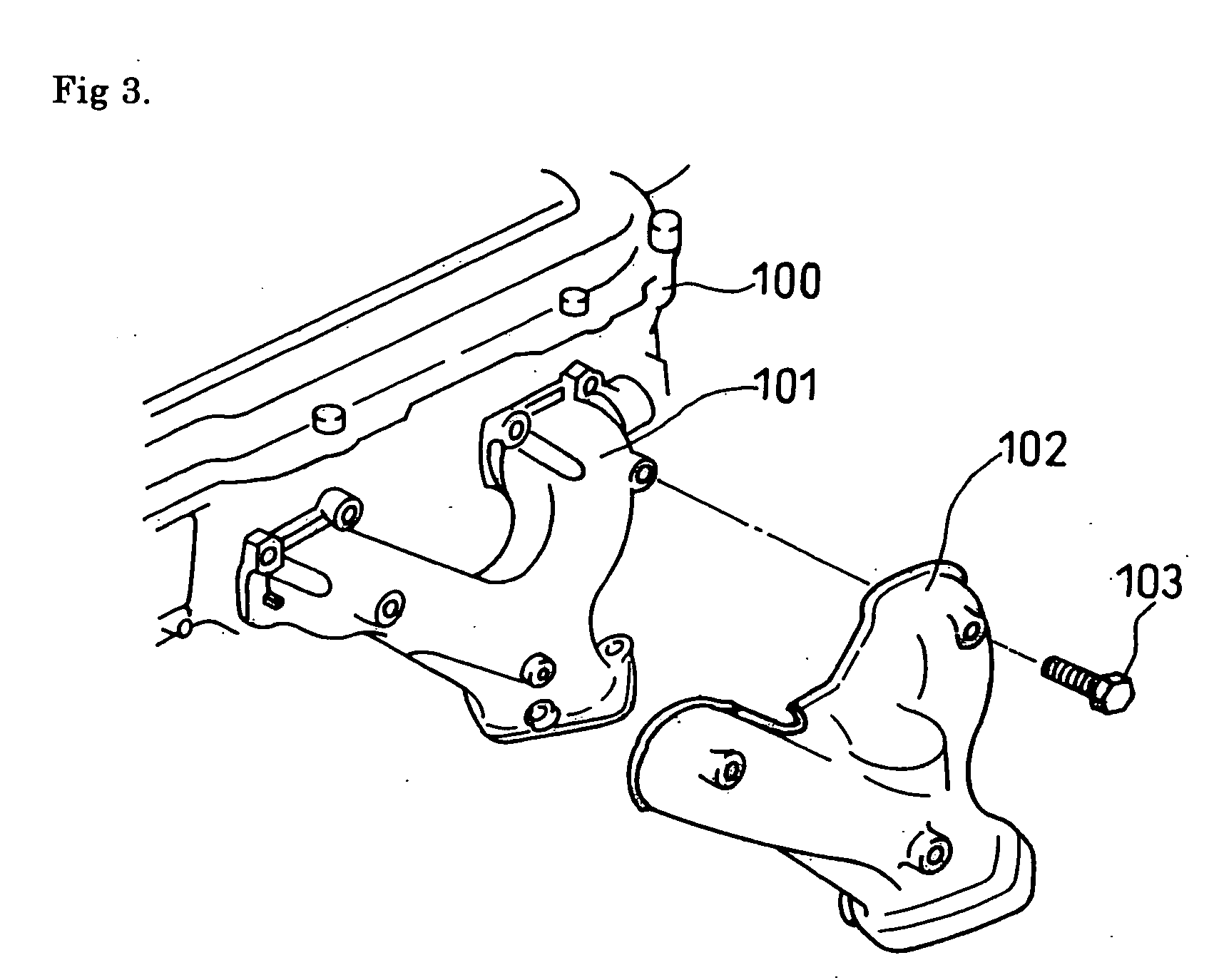
[0016] In the present invention, a vibration source can be exemplified by a motor vehicle and an exhaust manifold attached to the motor vehicle. Further, a heat source can be exemplified by the exhaust manifold of the motor vehicle. A vibration proofing heat shield plate 10 is fixed such as to cover at least a part of an exhaust manifold 20 while forming a gap with respect to a surface of the exhaust manifold 20 for reducing a heat radiation from the exhaust manifold 20 of an automotive engine.

[0017] The vibrating proofing heat shield plate 10 is provided with a vibration proofing heat shield plate main body portion 14, a collar member 11 positioned at an open hole of the vibration proofing heat shie...


PUM


Abstract

A vibration proofing heat shield plate (10) fixed such as to cover at least a part of a heat source (20) while forming a gap with respect to a surface of the heat source is provided with a vibration proofing heat shield plate main body portion (14), a collar member (11) positioned at an open hole (141) of the vibration proofing heat shield plate main body portion and provided with a pair of locking pieces (12, 13) fastened by bolt (17) to the heat source (20), a washer member (15) in which a portion interposed between a pair of locking pieces (12, 13) of the collar member (11) is formed in an approximately C-shaped cross section, and a joint member (16) joining the washer member (15) and the vibration proofing heat shield plate main body (14).

Description

TECHNICAL FIELD [0001] The present invention relates to a vibration proofing heat shield plate, for example, arranged around an exhaust manifold of an automotive engine. BACKGROUND ART [0002] As shown in FIG. 3, a combustion exhaust gas having a high temperature reaching some hundreds of degree flows through an inner portion of an exhaust manifold 101 of an automotive engine 100 in accordance with an operation of the engine 100. Accordingly, in order to prevent heat and vibration generated from the exhaust manifold 101 from being radiated into an engine room and an external portion of a vehicle, a vibration proofing heat shield plate 102 is provided around the exhaust manifold 101. When directly mounting the vibration proofing heat shield plate 102 to the exhaust manifold 101 by a bolt 103, the heat and the vibration of the exhaust manifold 101 are transmitted to the vibration proofing heat shield plate 102, and an effect obtained by placing the vibration proofing heat shield plate ...

Claims


Application Information

Patent Timeline
Patent Type & Authority Applications(United States)
IPC IPC(8): B60R13/08F01N13/08F01N13/10F01N13/14F01N13/18F02B77/11
CPCB60R13/0876F01N13/102F01N13/14F02B77/11F01N13/1855F01N2450/24F01N13/1811F01N13/08
Inventor NIWA, TAKAHIROISHIWA, SHUICHISUGAI, HIROTOAKIMOTO, KAZUYOMISHIMA, KAZUAKI
Owner NICHIAS CORP
Why Eureka
Try Eureka