Damper

a technology of adampers and abrasives, which is applied in the direction of shock absorbers, mechanical devices, door/window fittings, etc., can solve the problems of difficult to have a wide dynamic range of braking force, the braking force may become too small, etc., and achieve the effect of increasing the flow resistance of viscous fluid passing through the gap, reducing the operating performance, and reducing the operating cos

Active Publication Date: 2005-06-30
NIFCO INC
View PDF5 Cites 5 Cited by
  • Summary
  • Abstract
  • Description
  • Claims
  • Application Information

AI Technical Summary

Benefits of technology

[0008] According to the structure in the first aspect of the present invention, when a moving speed of the piston rod is relatively low, the gap between the inner member and the outer member is maintained to be large by an elastic force of the compression-coil spring. Accordingly, the flow resistance of the viscous fluid is small, so that operational performance is not lowered. When the moving speed of the piston rod exceeds a predetermined level and the resistance of the viscous fluid acting on the outer member exceeds an extension limit of the compression-coil spring, the coil spring contracts and the inner member moves into the outer member. Accordingly, the gap between the inner member and the outer member becomes narrower, and the flow resistance of the viscous fluid passing through the gap increases, thereby generating a large braking force. Specifically, in the present invention, it is possible to increase the proportion of the change in the braking force with respect to the change in the piston speed, thereby expanding the adaptable range of the damper.

Problems solved by technology

When the control force during a low speed is set appropriately, the braking force during a high speed may become too small.
Specifically, it is difficult to have a wide dynamic range of the braking force.

Method used


Image

  • Damper
  • Damper
  • Damper

Examples


Embodiment Construction

[0011] Hereunder, embodiments of the present invention will be explained with reference to the attached drawings.

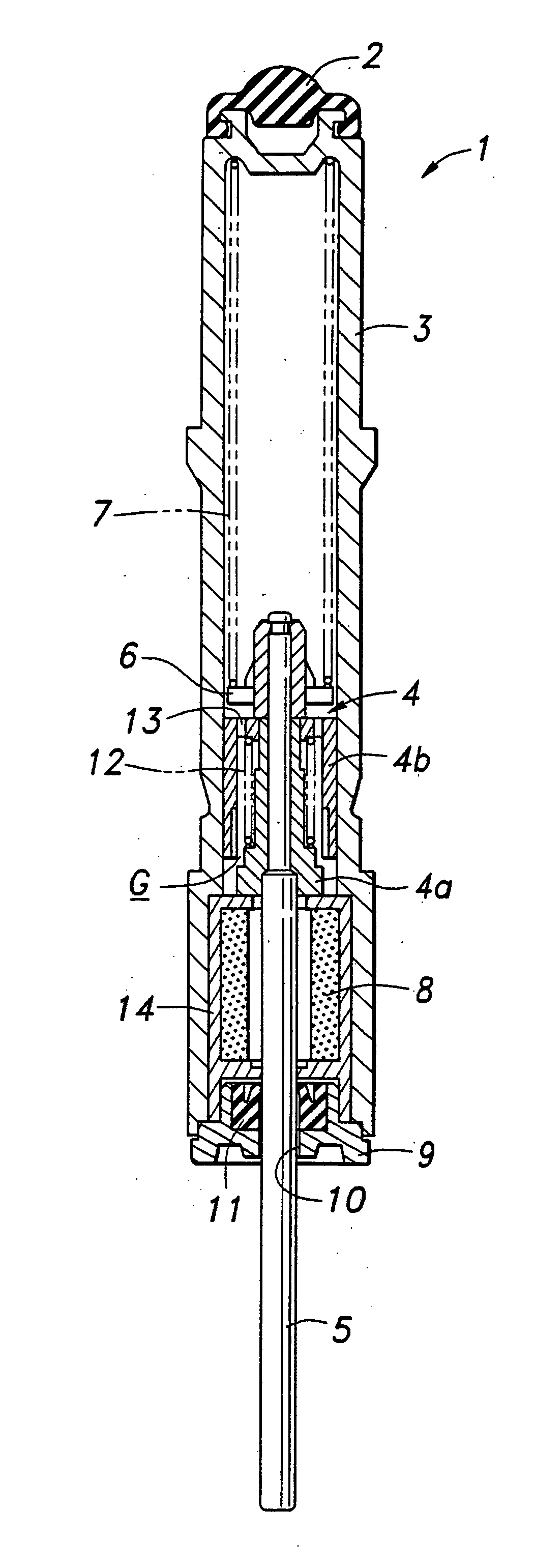
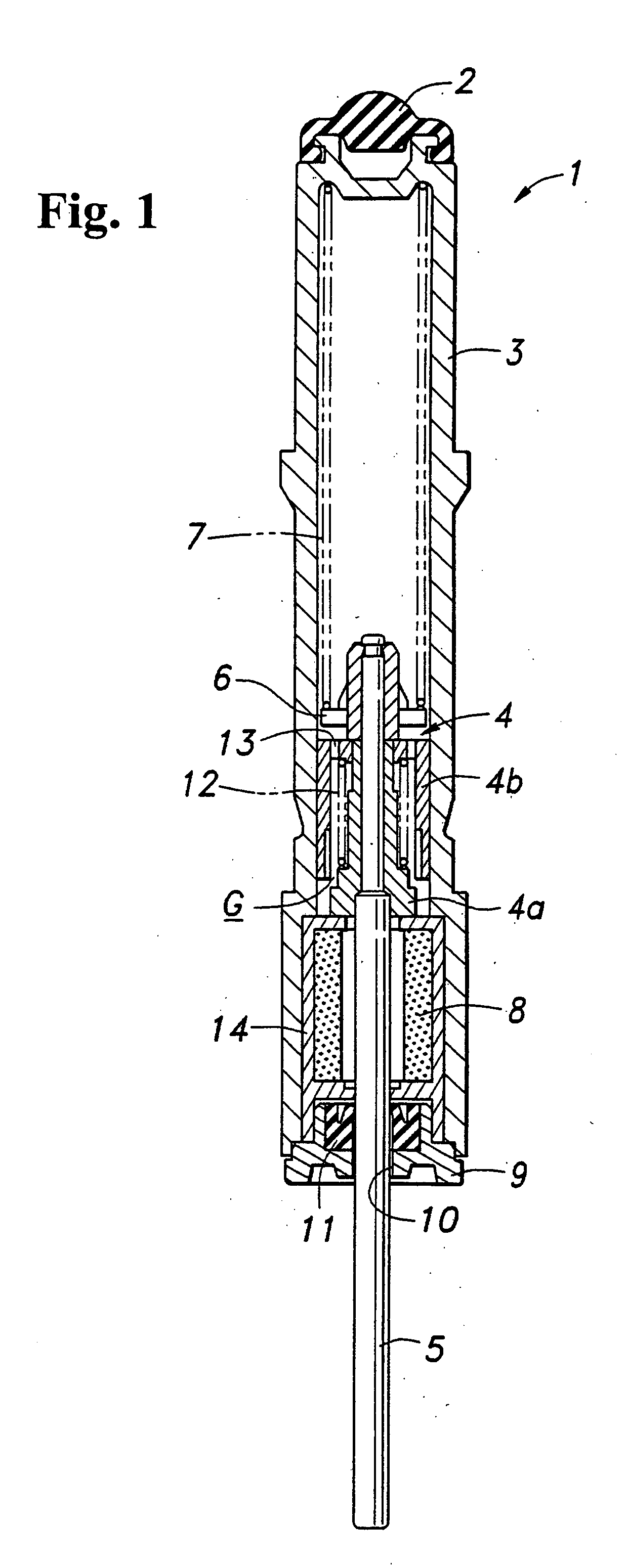
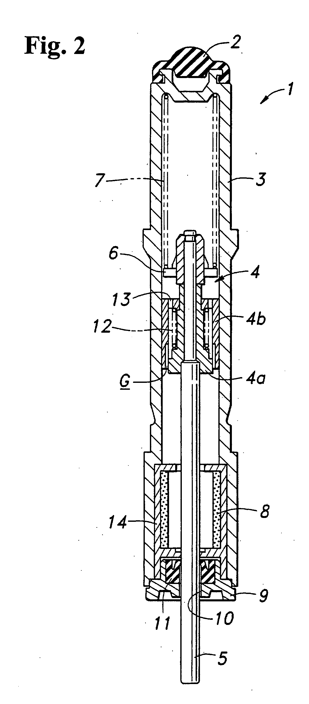
[0012]FIG. 1 is a cross sectional view of a damper according to the present invention. A damper 1 is formed of: a cylinder 3 with a closed bottom and a cushion rubber 2 placed on an outer-end surface; a piston 4 slidably fitted in the cylinder 3; a piston rod 5 connected to the piston 4; a first compression-coil spring 7 disposed between a spring retainer 6 provided on an inner end side of the piston rod 5 and an inner surface of a bottom wall of the cylinder 3; an accumulator 8 provided on a cylinder top side; and a cap 9 for closing the cylinder top. The piston rod 5 is inserted into a center hole 10 of the cap 9 via an oil seal 11 and projects outside the cylinder 3. Silicon oil with an appropriate viscosity is filled in the cylinder 3.

[0013] The piston 4 is formed of: an inner member 4a substantially integrated with the inner end side of the piston rod 5; and an out...


PUM


Abstract

A damper includes a piston with an orifice communicating in an axial direction and dividing a cylinder into two portions in the axial direction, and provides a braking force by resistance of a viscous fluid passing through the orifice when the piston moves inside the cylinder. The piston includes an inner member and an outer member movable in the inner member in the axial direction, which are loosely fitted with a gap for passing the viscous fluid. The inner and outer members are elastically urged with a spring in a direction wherein the inner and outer members are spaced. As the inner member moves to the outer member faster, the gap becomes narrower.

Description

BACKGROUND OF THE INVENTION AND RELATED ART STATEMENT [0001] The present invention relates to a damper and, more specifically, a damper in which a piston with orifice slides in a cylinder filled with a viscous fluid. [0002] In order to prevent a sound of sudden closing of a cabinet door and the like, a damper is provided in a doorstop portion of a cabinet for reducing a closing speed of the cabinet door. [0003] As the damper for generating a braking force mentioned above, there has been known a damper including: a cylinder filled with a viscous fluid; a piston dividing inside the cylinder into two portions in an axial direction and including an orifice communicating in the axial direction; and a piston rod connected to the piston. The damper generates the braking force (damping force) through resistance of the viscous fluid passing through the orifice when the piston moves together with the piston rod inside the cylinder in the axial direction (see Patent Reference No. 1). [0004] Pa...

Claims


Application Information

Patent Timeline
Patent Type & Authority Applications(United States)
IPC IPC(8): E05F3/04F16F9/19F16F9/32F16F9/34F16F9/512
CPCF16F9/5126F16F9/3405E05F3/04
Inventor TOMIJI, KATSUYASU
Owner NIFCO INC
Why Eureka
Try Eureka