
CTE-matched heat pipe

a heat pipe and heat sink technology, applied in the field of heat sinks, can solve the problems of unfavorable machining and stamping characteristics, and thermal energy that then must be transferred to the ambient environmen

Inactive Publication Date: 2005-06-30
THERMAL
View PDF73 Cites 20 Cited by
  • Summary
  • Abstract
  • Description
  • Claims
  • Application Information

AI Technical Summary

Benefits of technology

[0011] In a further embodiment, a heat pipe is provided that includes a tubular body having a central passageway with a wick disposed on at least an evaporator portion of the central passageway. The wick is at least partially saturated with a working fluid. A layered composite low CTE base seals off the evaporator portion of the central passag

Problems solved by technology

It is known that certain classes of semiconductor devices consume substantial amounts of power, which results in excess thermal energy that then must be transferred to the ambient environment.
Since heat is often dissipated to room temperature air, and the silicon constructed semiconductor has a finite upper bound on its operating temperature, package-related thermal resistance is becoming a limiting factor in the ability to dissipate the waste heat.
Some disadvantages of the alloy substrate include expense, unfavorable machining and stamping characteristics, and a fairly low thermal conductivity.
Some disadvantages of the ductile braze alloy include a limited fatigue life, which eventually results in failure due to delamination of the joint.
Such devices almost always operate under conditions of periodic fluctuating electrical load, which leads to periodic fluctuations in thermal load and mechanical stresses in the joint.
None of the foregoing techniques have been found to be completely satisfactory or have been successfully applied to heat pipe cooling devices.

Method used


Image

  • CTE-matched heat pipe
  • CTE-matched heat pipe
  • CTE-matched heat pipe

Examples


Embodiment Construction

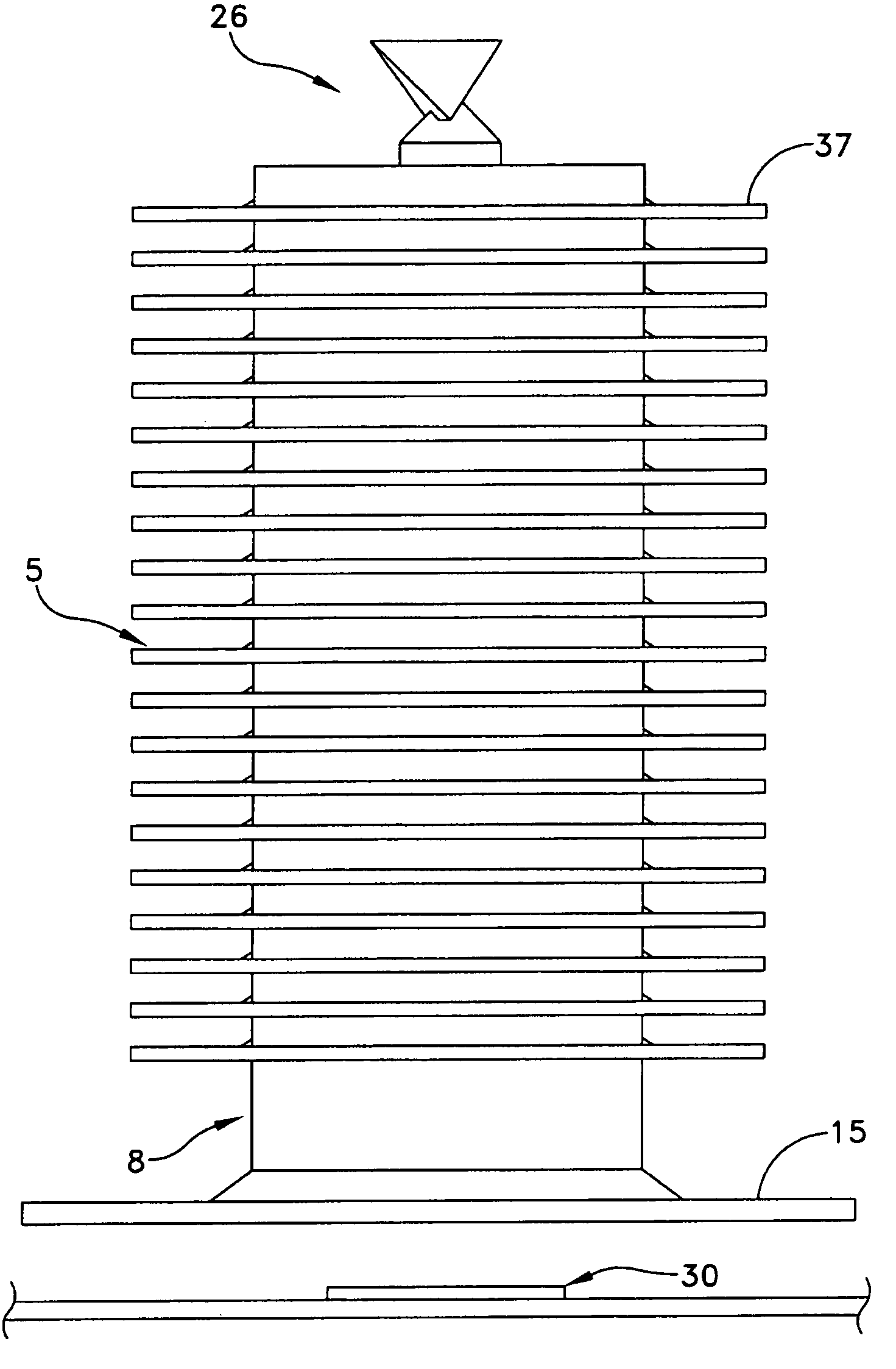
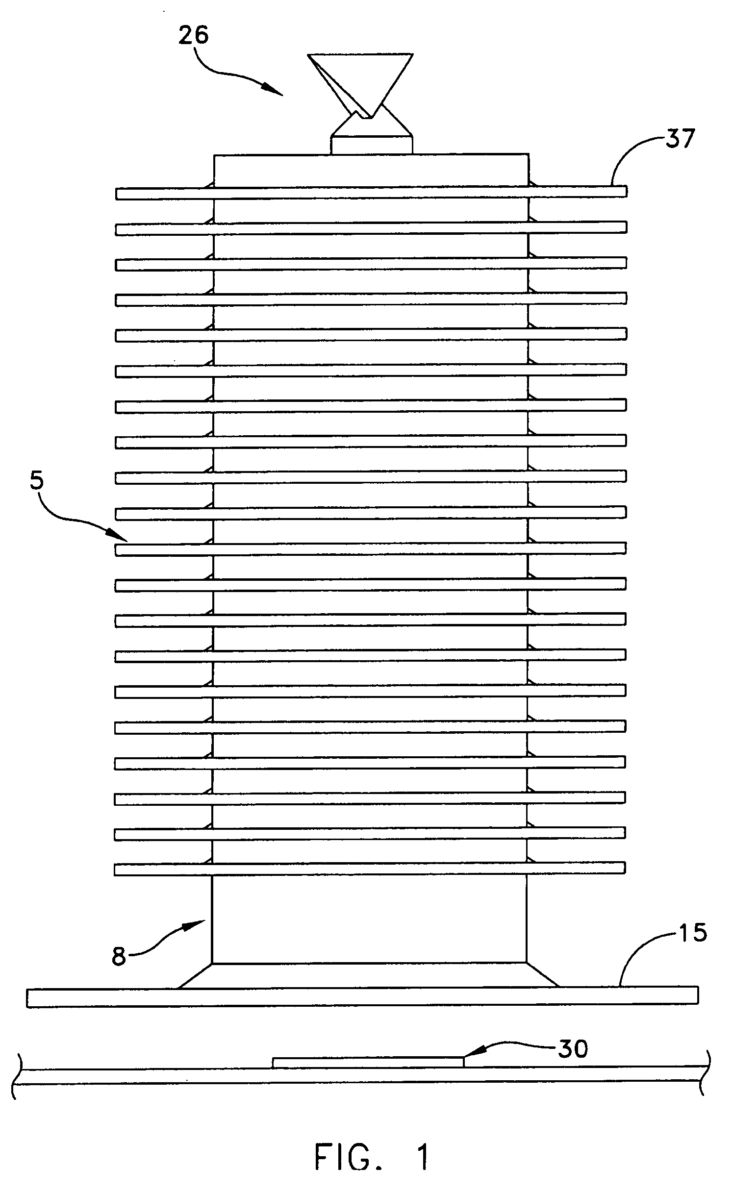
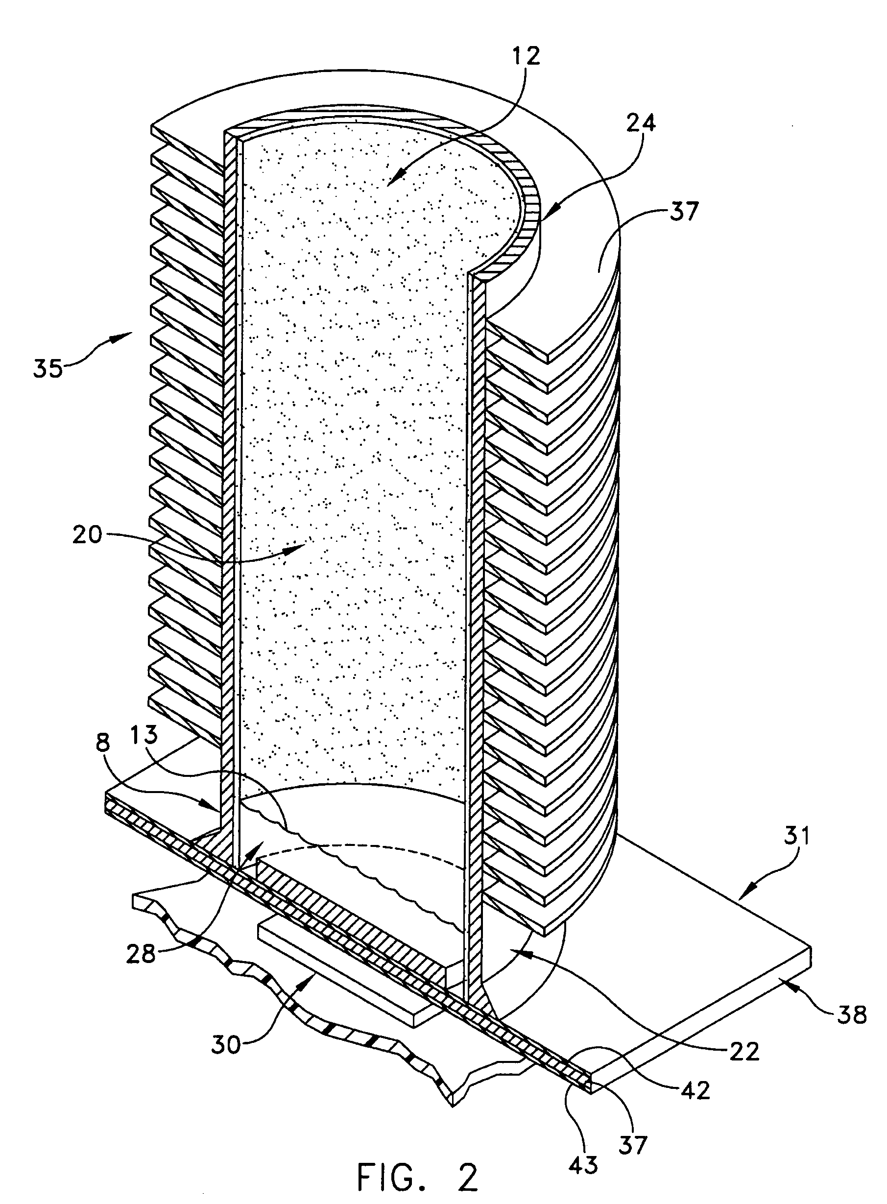
[0045] This description of preferred embodiments is intended to be read in connection with the accompanying drawings, which are to be considered part of the entire written description of this invention. The drawing figures are not necessarily to scale and certain features of the invention may be shown exaggerated in scale or in somewhat schematic form in the interest of clarity and conciseness. In the description, relative terms such as “horizontal,”“vertical,”“up,”“down,”“top” and “bottom” as well as derivatives thereof (e.g., “horizontally,”“downwardly,”“upwardly,” etc.) should be construed to refer to the orientation as then described or as shown in the drawing figure under discussion. These relative terms are for convenience of description and normally are not intended to require a particular orientation. Terms including “inwardly” versus “outwardly,”“longitudinal” versus “lateral” and the like are to be interpreted relative to one another or relative to an axis of elongation, o...


PUM


Abstract

Heat sinks having a mounting surface with a coefficient of thermal expansion matching that of silicon are disclosed. Heat pipes having layered composite or integral composite low coefficient of expansion heat sinks are disclosed that can be mounted directly to silicon semiconductor devices.

Description

CROSS-REFERENCE TO RELATED APPLICATIONS [0001] This application is a continuation-in-part of copending U.S. patent application Ser. No. 10 / 924,586, filed Aug. 24, 2004, which is itself a continuation application of U.S. patent application Ser. No. 10 / 458,168, filed Jun. 10, 2003, now issued as U.S. Pat. No. 6,793,009, and is also related to U.S. Provisional Patent Applications Nos. 60 / 561,436, filed Apr. 12, 2004, and 60 / 574,158, filed May 25, 2004.FIELD OF THE INVENTION [0002] The present invention relates to heat sinks having mounting surfaces for semiconductors, and more particularly to such heat sinks which include one or more mounting surfaces having a coefficient of thermal expansion that matches or nearly matches silicon. BACKGROUND OF THE INVENTION [0003] It is known that certain classes of semiconductor devices consume substantial amounts of power, which results in excess thermal energy that then must be transferred to the ambient environment. This waste heat is typically c...

Claims


Application Information

Patent Timeline
IPC IPC(8): F28D15/02H01L23/427
CPCF28D15/02H01L23/427H01L2924/3011H01L2924/0002H01L2924/00F28D15/0275F28D15/0283F28D15/04F28F1/24F28F21/02F28F21/081F28F21/085F28F2220/00F28F1/003
Inventor SARRAF, DAVIDHARTENSTINE, JOHNTOTH, JEROMEGARNER, SCOTT
Owner THERMAL
Learn More