Co-injection nozzle, method of its use, and resulting golf ball

a golf ball and injection nozzle technology, applied in the field of golf balls, can solve the problems of difficult control, low spin rate, increased distance, etc., and achieve the effect of minimizing or eliminating waste and facilitating material flow

Inactive Publication Date: 2005-06-30
ACUSHNET CO
View PDF67 Cites 23 Cited by
  • Summary
  • Abstract
  • Description
  • Claims
  • Application Information

AI Technical Summary

Benefits of technology

[0049] The nozzle includes a nozzle body, an inner nozzle, and an outer nozzle. The inner nozzle is placed within the outer nozzle, and the subassembly is attached to the nozzle body. The outer surface of the inner nozzle contains radial grooves to facilitate material

Problems solved by technology

Further, such a combination imparts a high initial velocity to the ball which results in increased distance.
Due to their hardness however, these balls have a relatively low spin rate, which makes them difficult to control, particularly on shorter approach shots.
Because these materials are very rigid, many two piece balls have a hard “feel” when struck with a club.
Moreover, as a result of their more complex structure, wound balls generally require a longer time to manufacture and are more expensive to produce than a two piece ball.
The color instability caused by both thermo-oxidative degradation and photodegradation typically results in a “y

Method used


Image

  • Co-injection nozzle, method of its use, and resulting golf ball
  • Co-injection nozzle, method of its use, and resulting golf ball
  • Co-injection nozzle, method of its use, and resulting golf ball

Examples


Embodiment Construction

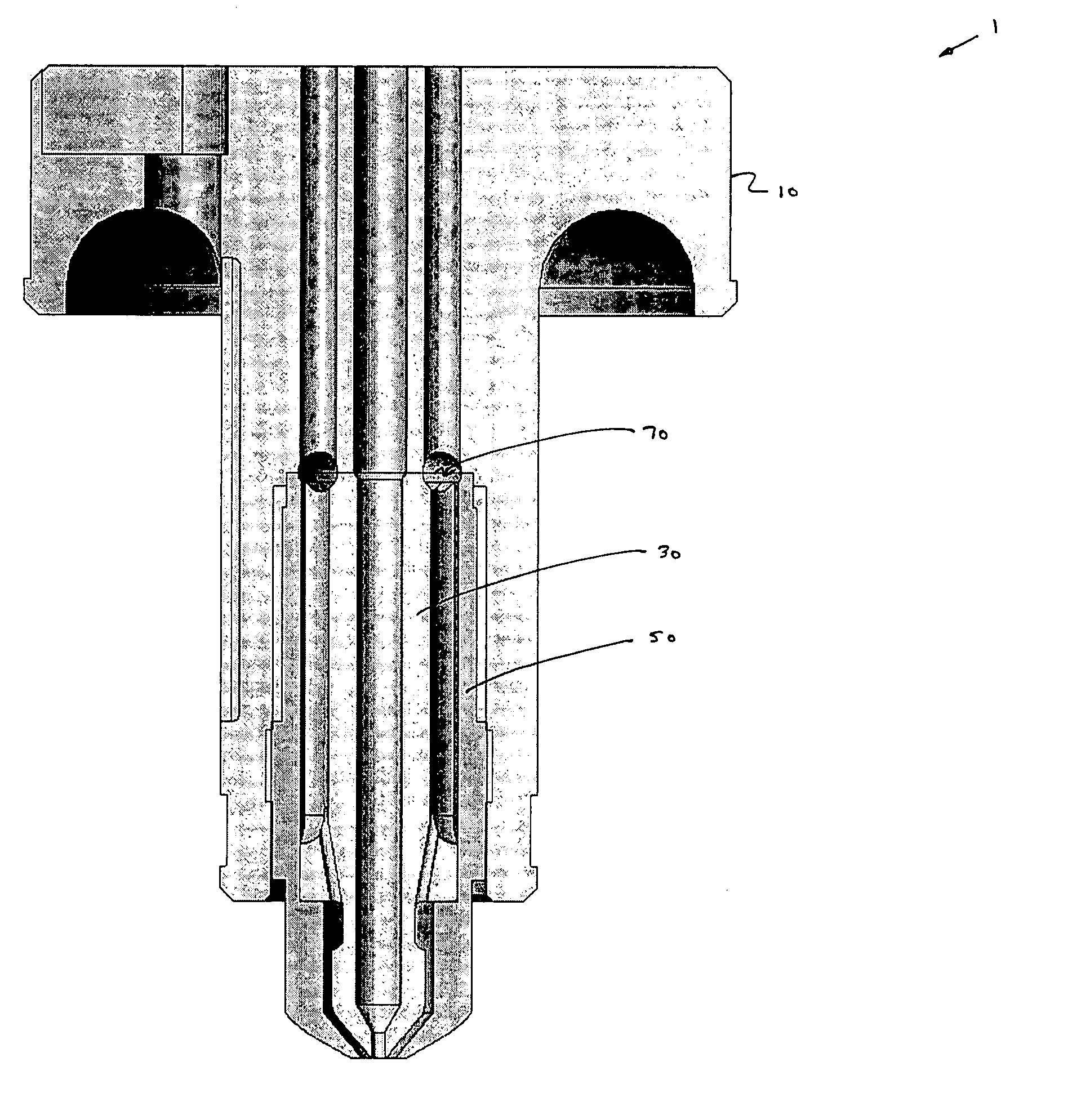
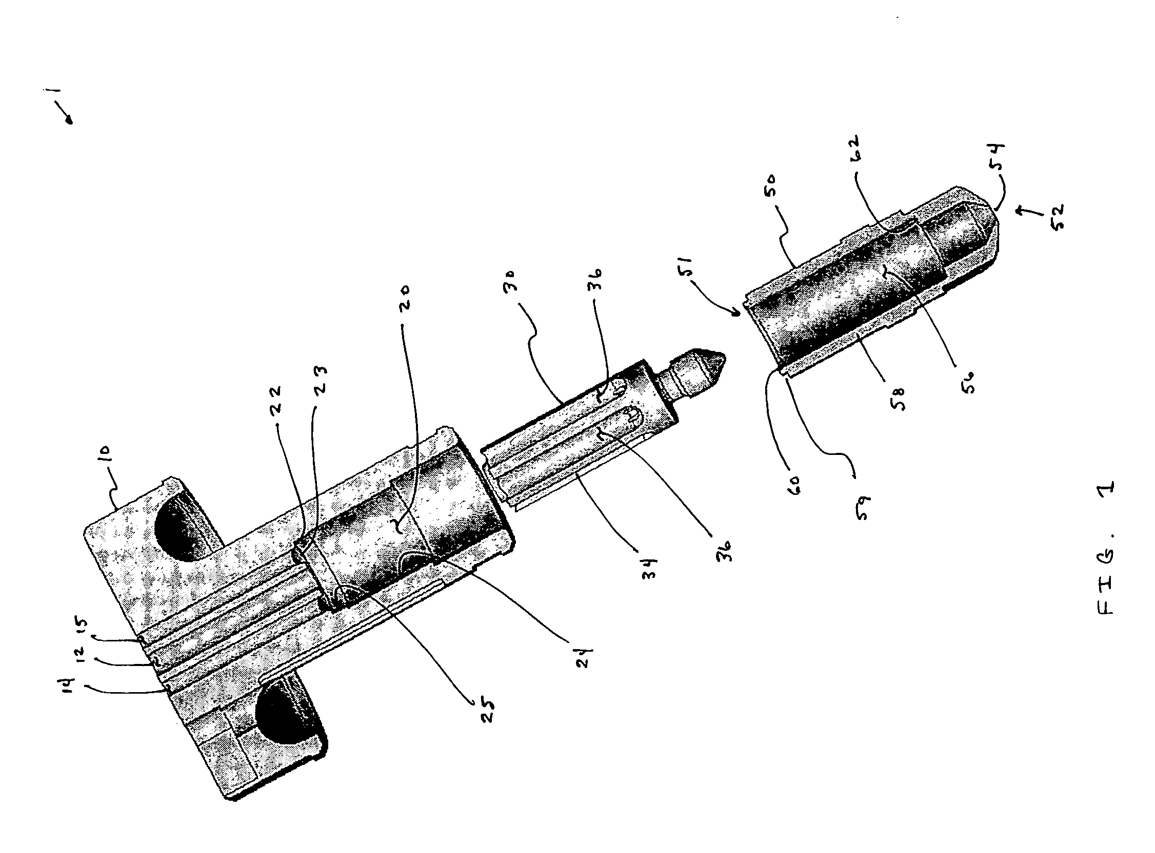
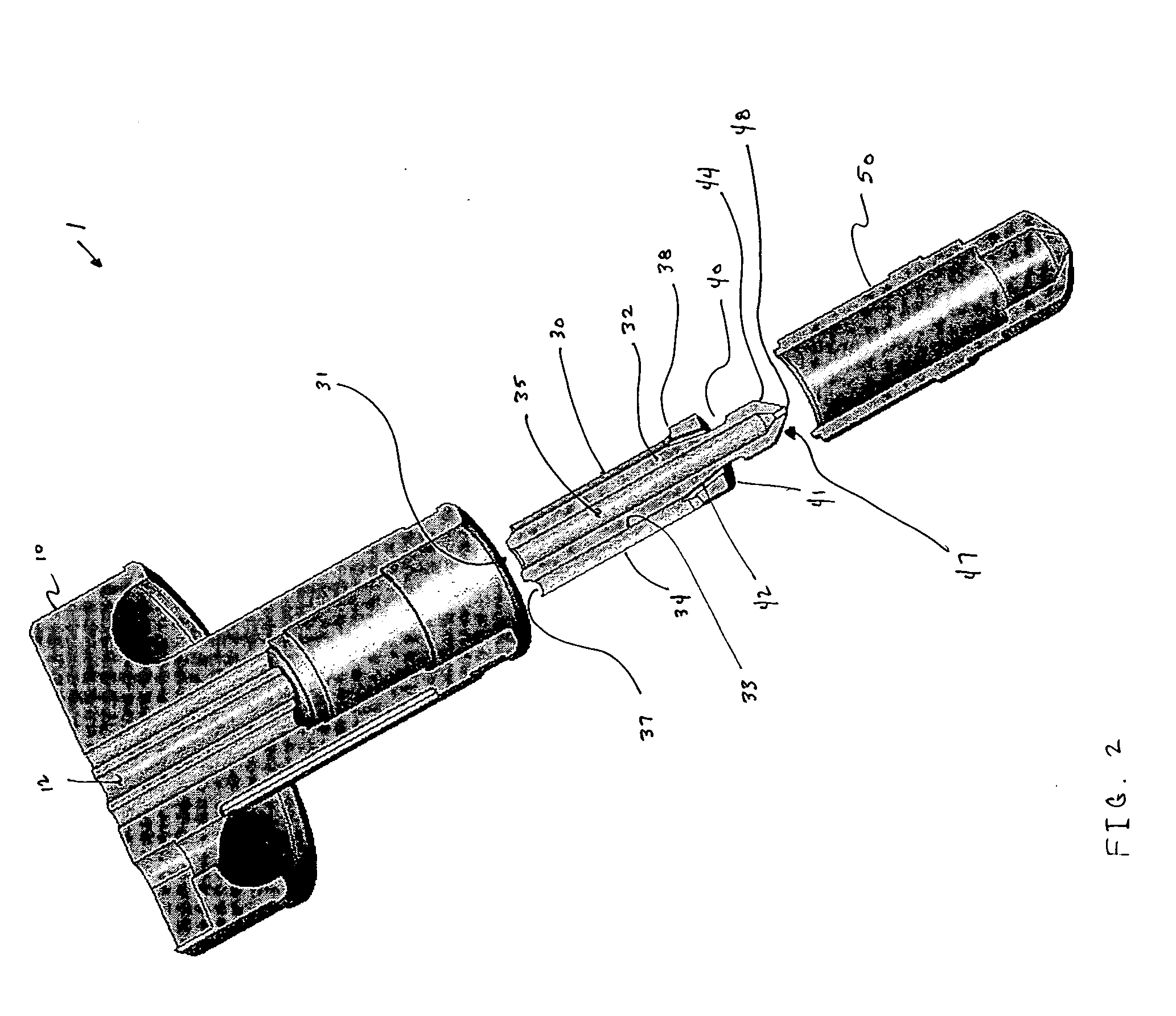
[0062]FIG. 1 shows an exploded and partially cross-sectional view of a nozzle 1 of the present invention. FIG. 2 shows an exploded and fully cross-sectional view of nozzle 1. Nozzle 1 includes a nozzle body 10, an inner nozzle 30, and an outer nozzle 50.

[0063] Nozzle body 10 includes a counter bore 20 defining an interior region with an inner wall 24. Nozzle body 10 further includes a first passageway 12, a second passageway 14, and, optionally, a third passageway 15 extending through nozzle body 10 from a distal end thereof to counter bore 20. Counter bore 20 defines a ledge 22 that contains an annular groove 23 therein. Annular groove 22, which preferably has a hemispherical shape, is in fluid communication with nozzle body second and third passageways 14, 15. A portion 25 of wall 24 is threaded for receiving outer nozzle section 50.

[0064] Outer nozzle 50 is removably and fixedly coupled to nozzle body 10 at a first end 51 and has an orifice 54 at a second end 52. As used herein...


PUM

PropertyMeasurementUnit
Diameteraaaaaaaaaa
Diameteraaaaaaaaaa
Diameteraaaaaaaaaa

Abstract

A nozzle for an injection molding machine is disclosed. The nozzle includes a nozzle body, an inner nozzle, and an outer nozzle. The nozzle defines two independent flow paths therethrough. The nozzle can simultaneously discharge two materials. A method of using the nozzle and a resulting golf ball product are also disclosed.

Description

BACKGROUND OF THE INVENTION [0001] 1. Field of the Invention [0002] The present invention relates generally to golf balls, and more specifically, to a method of making a golf ball with a multi-layer cover. In particular, the present invention relates to a method of making a golf ball having a cover with three layers comprised of at least two different materials. [0003] 2. Description of the Related Art [0004] Conventional golf balls typically include at least a core and a cover, and can be divided into three general types or groups: (1) two piece balls, (2) wound balls (also know as three piece balls), and (3) multilayer balls. The difference in play characteristics resulting from these different types of constructions can be quite significant. [0005] Balls having a two piece construction are generally most popular with the recreational golfer because they provide a very durable ball while also providing maximum distance. Two piece balls are made with a single solid core, usually fo...

Claims


Application Information

Patent Timeline
IPC IPC(8): B29C45/16B29C45/22
CPCB29C45/1642B29C45/1603
Inventor PUNIELLO, PAUL A.CAVALLARO, CHRISTOPHERGRACE, CHRISTOPHER T.CRANDALL, DAVID J.HEPLER, DOUGLAS C.
Owner ACUSHNET CO
Why Eureka
Try Eureka