
Movable barrier operator

a technology of operator and moving barrier, which is applied in the direction of electric programme control, dynamo-electric converter control, instruments, etc., can solve the problems of high impulse force application, and achieve the effect of less momentum, smooth and quiet stop, and safer barrier operator movemen

Inactive Publication Date: 2005-06-30
THE CHAMBERLAIN GRP INC
View PDF5 Cites 6 Cited by
  • Summary
  • Abstract
  • Description
  • Claims
  • Application Information

AI Technical Summary

Benefits of technology

[0015] A movable barrier operator having an electric motor for driving a garage door, a gate or other barrier is operated from a source of AC current. The movable barrier operator includes circuitry for automatically detecting the incoming AC line voltage and frequency of the alternating current. By automatically detecting the incoming AC line voltage and determining the frequency, the operator can automatically configure itself to certain user preferences. This occurs without either the user or the installer having to adjust or program the operator. The movable barrier operator includes a worklight for illuminating its immediate surroundings such as the interior of a garage. The barrier operator senses the power line frequency (typically 50 Hz or 60 Hz) to automatically set an appropriate shut-off time for a worklight. Because the power line frequency in Europe is 50 Hz and in the U.S. is 60 Hz, sensing the power line frequency enables the operator to configure itself for either a European or a U.S. market with no user or installer modifications. For U.S. users, the worklight shut-off time is set to preferably 4½ minutes; for European users, the worklight shut-off time is set to preferably 2½ minutes. Thus, a single barrier movement operator can be sold in two different markets with automatic setup, saving installation time.
[0016] The movable barrier operator of the present invention automatically detects if an optional flasher module is present. If the module is present, when the door is commanded to move, the operator causes the flasher module to operate. With the flasher module present, the operator also delays operation of the motor for a brief period, say one or two seconds. This delay period with the flasher module blinking before door movement provides an added safety feature to users which warns them of impending door travel (e.g. if activated by an unseen transmitter).
[0017] The movable barrier operator of the present invention drives the barrier, which may be a door or a gate, at a variable speed. After motor start, the electric motor reaches a preferred initial speed of 20 percent of the full operating speed. The motor speed then increases slowly in a linearly continuous fashion from 20 percent to 100 percent of full operating speed. This provides a smooth, soft start without jarring the transmission or the door or gate. The motor moves the barrier at maximum speed for the largest portion of its travel, after which the operator slowly decreases speed from 100 percent to 20 percent as the barrier approaches the limit of travel, providing a soft, smooth and quiet stop. A slow, smooth start and stop provides a safer barrier movement operator for the user because there is less momentum to apply an impulse force in the event of an obstruction. In a fast system, relatively high momentum of the door changes to zero at the obstruction before the system can actually detect the obstruction. This leads to the application of a high impulse force. With the system of the invention, a slower stop speed means the system has less momentum to overcome, and therefore a softer, more forgiving force reversal. A slow, smooth start and stop also provide a more aesthetically pleasing effect to the user, and when coupled with a quieter DC motor, a barrier movement operator which operates very quietly.

Problems solved by technology

This leads to the application of a high impulse force.

Method used


Image

  • Movable barrier operator
  • Movable barrier operator
  • Movable barrier operator

Examples


Embodiment Construction

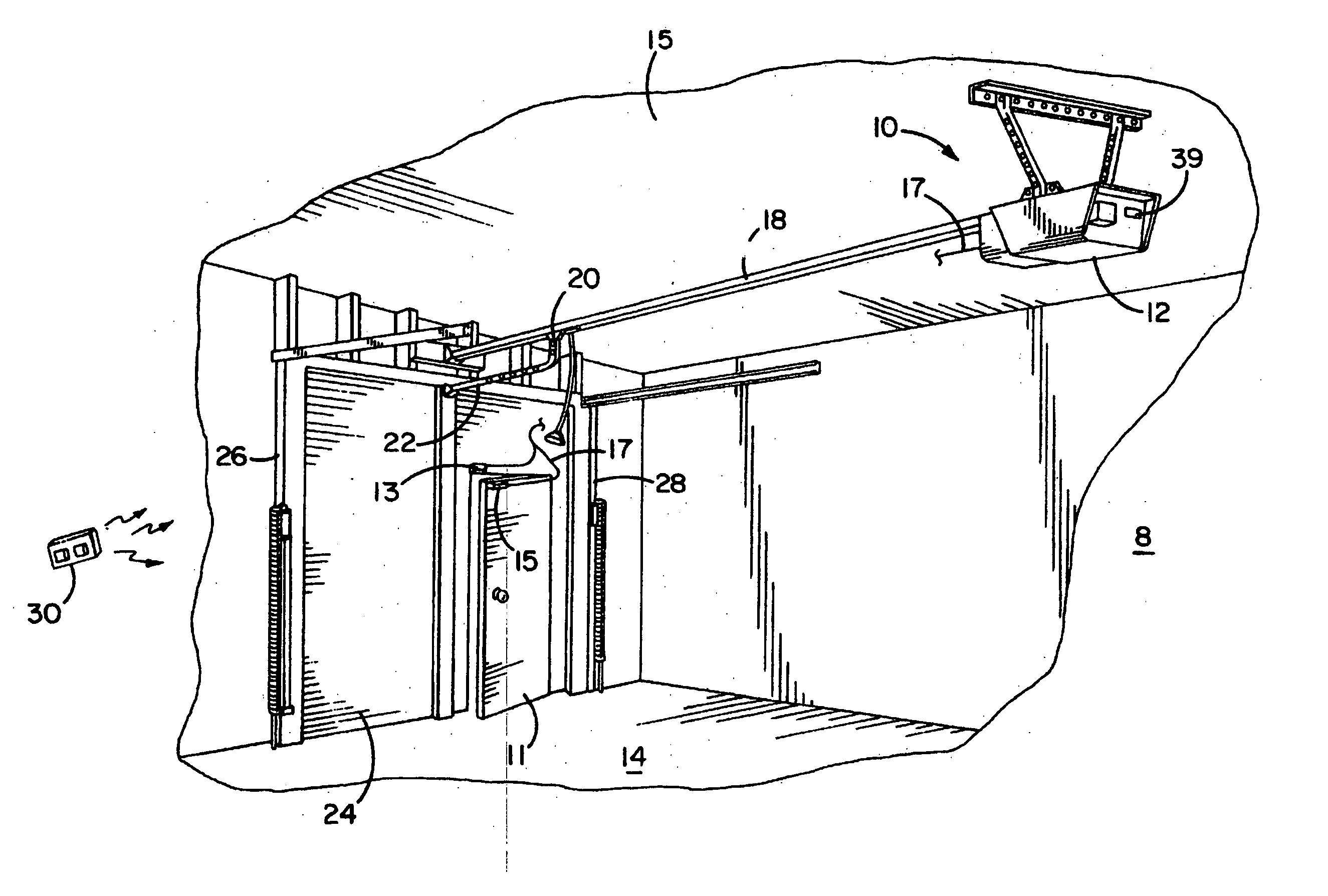
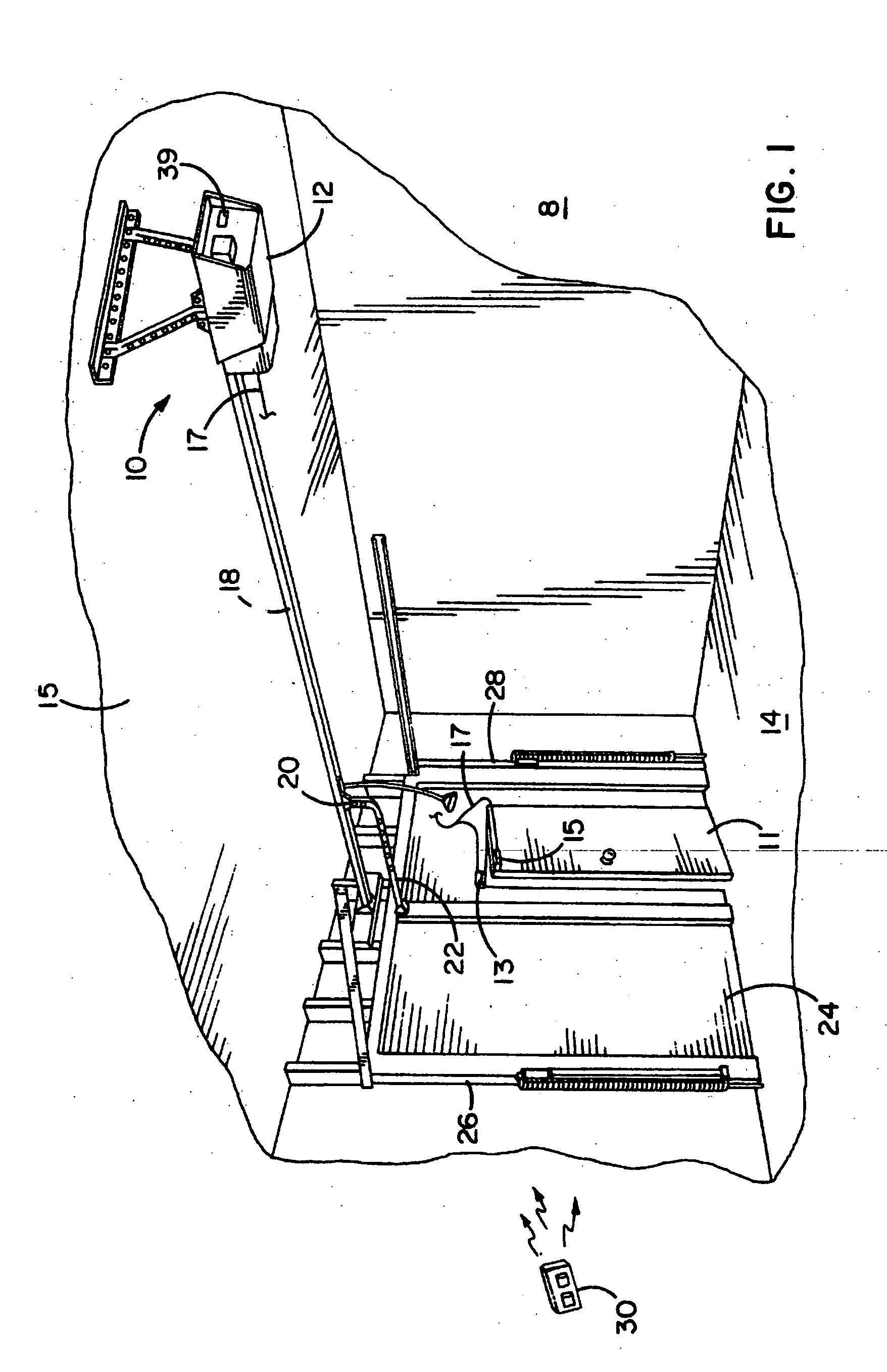
[0045] Referring now to the drawings and especially to FIG. 1, a movable barrier or garage door operator system is generally shown therein and referred to by numeral 8. The system 8 includes a movable barrier operator or garage door operator 10 having a head unit 12 mounted within a garage 14. More specifically, the head unit 12 is mounted to a ceiling 15 of the garage 14. The operator 10 includes a transmission 18 extending from the head unit 12 with a releasable trolley 20 attached. The releasable trolley 20 releasably connects an arm 22 extending to a single panel garage door 24 positioned for movement along a pair of door rails 26 and 28.

[0046] The system 8 includes a hand-held RF transmitter unit 30 adapted to send signals to an antenna 32 (see FIG. 4) positioned on the head unit 12 and coupled to a receiver within the head unit 12 as will appear hereinafter. A switch module 39 is mounted on the head unit 12. Switch module 39 includes switches for each of the commands availabl...


PUM


Abstract

A movable barrier operator having improved safety and energy efficiency features automatically detects line voltage frequency and uses that information to set a worklight shut-off time. The operator automatically detects the type of door (single panel or segmented) and uses that information to set a maximum speed of door travel. The operator moves the door with a linearly variable speed from start of travel to stop for smooth and quiet performance. The operator provides for full door closure by driving the door into the floor when the DOWN limit is reached and no auto-reverse condition has been detected. The operator provides for user selection of a minimum stop speed for easy starting and stopping of sticky or binding doors.

Description

[0001] This application is a continuation of application Ser. No. 09 / 804,407 filed Mar. 12, 2001, which is a continuation of application Ser. No. 09 / 535,221 filed Mar. 27, 2000, now U.S. Pat. No. 6,229,276, which is a division-of application Ser. No. 09 / 161,840 filed Sep. 28, 1998, now U.S. Pat. No. 6,172,475, which are all incorporated herein by reference.BACKGROUND OF THE INVENTION [0002] This invention relates generally to movable barrier operators for operating movable barriers or doors. More particularly, it relates to garage door operators having improved safety and energy efficiency features. [0003] Garage door operators have become more sophisticated over the years providing users with increased convenience and security. However, users continue to desire further improvements and new features such as increased energy efficiency, ease of installation, automatic configuration, and aesthetic features, such as quiet, smooth operation. [0004] In some markets energy costs are signi...

Claims


Application Information

Patent Timeline
Patent Type & Authority Applications(United States)
IPC IPC(8): B23Q35/00E05F15/00E05F15/10E05F15/12E05F15/14E05F15/16E05F15/20E05F15/60G05B5/00G05B9/00G05B19/42G05B23/02H02H7/08H02P1/00H02P1/04H02P3/00H02P7/00H05B37/02H05B39/04
CPCE05D15/38E05Y2201/726E05Y2400/452E05Y2400/456E05Y2400/59E05Y2400/822E05F15/684E05F15/00Y10S388/904Y10S388/909E05Y2800/00E05F15/603E05F15/668E05Y2900/106E05Y2400/83
Inventor FITZGIBBON, JAMES J.WANIS, PAUL E.WILLMOTT, COLIN
Owner THE CHAMBERLAIN GRP INC
Learn More