Microstrip cross-coupled bandpass filter with asymmetric frequency characteristic

a bandpass filter and cross-coupling technology, applied in the field of bandpass filters, can solve the problems of increasing the need for low loss and high attenuation characteristics of bandpass filters, the restriction of their design, and the inability to meet the demand of millimeter-wave home networks. achieve the effect of low manufacturing cost, high attenuation pole characteristics, and low loss

Inactive Publication Date: 2005-06-30
ELECTRONICS & TELECOMM RES INST
View PDF10 Cites 11 Cited by
  • Summary
  • Abstract
  • Description
  • Claims
  • Application Information

AI Technical Summary

Benefits of technology

[0025] It is an advantage of the present invention to provide a microstrip cross-coupled bandpass filter with an asymmetric frequency characteristic, which can be miniaturized and fabricated by an optimized fabrication process at a low manufacturing cost, and provide low loss and high attenuation pole characteristics.
[0026] It is another advantage of the present invention to provide a bandpass filter that is designed unrestrictedly, has a simplified pattern such that it can be fabricated by an optimized process at a low manufacturing cost, and is suitable for an system on package (SOP) of a millimeter-wave home network system and module.
[0027] In one aspect of the present invention, a microstrip cross-coupled bandpass filter comprises: an input port through which a signal is input; an output port through which a select signal of a characteristic band is output; and a plurality of resonators including at least a first resonator that is electric-coupled with at least a part of the input port and a second resonator that is electric-coupled with at least a part of the output port. Magnetic coupling is formed according to a cross coupling gap corresponding to the distance between the first and second resonators.
[0028] The bandpass filter can further comprise a third resonator that is electric-coupled with at least a part of the first resonator and at least a part of the second resonator.
[0029] The cross coupling gap forming the magnetic coupling generates an attenuation pole on the high side of a passband.
[0030] The attenuation frequency of the attenuation pole can be varied with a variation in the distance of the cross coupling gap.

Problems solved by technology

Although the waveguide component has low loss and high attenuation characteristics, its cost, size, and weight cannot satisfy the millimeter-wave home network's demand.
However, the bandpass filter has only a single attenuation pole and there is a restriction on its design caused by the value of the dielectric constant.
In addition, low loss and high attenuation characteristics of the bandpass filter are increasingly needed.

Method used


Image

  • Microstrip cross-coupled bandpass filter with asymmetric frequency characteristic
  • Microstrip cross-coupled bandpass filter with asymmetric frequency characteristic
  • Microstrip cross-coupled bandpass filter with asymmetric frequency characteristic

Examples


first embodiment

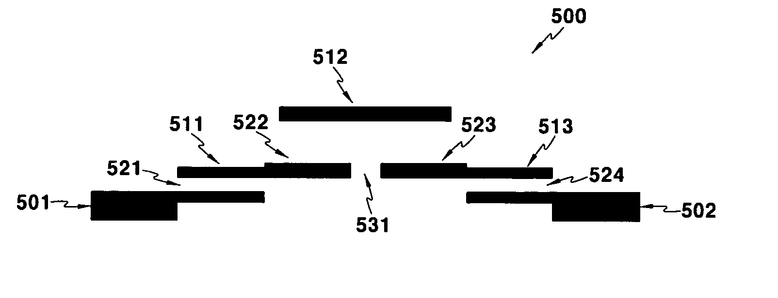
[0062] In the bandpass filter according to the present invention, the ports and the resonators are mainly electric-coupled, and the λ / 2 transmission line input resonator 511 and the λ / 2 transmission line output resonator 513 are magnetic-coupled. Accordingly, an attenuation pole is formed on the high side of a passband, and an attenuation pole characteristic and frequency are controlled by the cross coupling gap 531.

second embodiment

[0063]FIG. 6 shows a pattern of a microstrip cross-coupled bandpass filter that includes λ / 2 transmission line resonators and has asymmetric frequency characteristic according to the present invention.

[0064] The bandpass filter 600 according to the second embodiment of the present invention is distinguished from the bandpass filter according to the first embodiment of the present invention in that the bandpass filter 600 has a cross coupling line 641 and coupling 642 of input / output ports and the cross coupling line 641. That is, the bandpass filter 600 includes the cross coupling gap and cross coupling line.

[0065] Specifically, the bandpass filter 600 includes λ / 2 transmission line resonators that are parallel coupled filters 611, 612, and 613, an input port 601, an output port 602, electric coupling 621 between the input port 601 and the λ / 2 transmission line input resonator 611, electric coupling 622 between the λ / 2 transmission line input resonator 611 and the λ / 2 transmission ...


PUM


Abstract

A microstrip cross coupling bandpass filter includes an input port, an input resonator, an output port, and an output resonator. The input port and the input resonator are electric-coupled, and the output port and the output resonator are electric-coupled. A cross coupling gap corresponding to the distance between the input and output resonators forms magnetic coupling. The bandpass filter further includes a cross coupling line electric-coupled with the input and output ports. The cross coupling gap generates an attenuation pole on the high side of a passband. The attenuation frequency of the attenuation pole can be varied with the distance of the cross coupling gap. The cross coupling line generates an attenuation pole on the high and low sides of the passband.

Description

CROSS REFERENCE TO RELATED APPLICATION [0001] This application claims priority to and the benefit of Korea Patent Application No. 2003-96309 filed on Dec. 24, 2003 in the Korean Intellectual Property Office, the entire content of which is incorporated herein by reference. BACKGROUND OF THE INVENTION [0002] (a) Field of the Invention [0003] The present invention relates to a bandpass filter, and more particularly, to a microstrip bandpass filter with an asymmetric frequency characteristic, which includes cross coupling and resonators. [0004] (b) Description of the Related Art [0005] Recently, a component in the form of a waveguide has been generally used as a bandpass filter in a millimeter-wave home network system. Although the waveguide component has low loss and high attenuation characteristics, its cost, size, and weight cannot satisfy the millimeter-wave home network's demand. [0006] A conventional microstrip cross-coupled bandpass filter that includes resonators and has an asym...

Claims


Application Information

Patent Timeline
Patent Type & Authority Applications(United States)
IPC IPC(8): H01P1/203
CPCH01P1/203
Inventor JUN, DONG-SUKLEE, HONG-YEOLLEE, SANG-SEOKKO, KYOUNG-SUKKIM, DONG-YOUNGCHO, KYOUNG-IK
Owner ELECTRONICS & TELECOMM RES INST
Why Eureka
Try Eureka