Connection apparatus for parallel optical interconnect module and parallel optical interconnect module using the same

a technology of parallel optical interconnection and connection apparatus, which is applied in the direction of optics, semiconductor devices, instruments, etc., can solve the problems of reducing system operation efficiency, difficult system integration, and inability to achieve satisfactory efficiency, so as to facilitate coupling with optical fibers, improve structure, and minimize optical coupling losses

Inactive Publication Date: 2005-06-30
ELECTRONICS & TELECOMM RES INST
View PDF5 Cites 70 Cited by
  • Summary
  • Abstract
  • Description
  • Claims
  • Application Information

AI Technical Summary

Benefits of technology

[0018] According to the present invention, the present invention provides a parallel optical interconnect module with an improved structure which faci

Problems solved by technology

However, with the high-capacity and the increase of transfer rate of information such as in an advanced telecommunication system constituted with a high-capacity parallel computer or a 1 or more Tb/s class asynchronous transfer mode (ATM) switching system and so on, if used such metal cable, there is caused an electrical problem such as skewing or electromagnetic interference (EMI) and so on, thereby reducing operational efficiency of the

Method used


Image

  • Connection apparatus for parallel optical interconnect module and parallel optical interconnect module using the same
  • Connection apparatus for parallel optical interconnect module and parallel optical interconnect module using the same
  • Connection apparatus for parallel optical interconnect module and parallel optical interconnect module using the same

Examples


Embodiment Construction

[0029] The present invention will now be described more fully hereinafter with reference to the accompanying drawings, in which exemplary embodiments of the invention are shown. This invention may, however, be embodied in different forms and should not be construed as limited to the embodiments set forth herein. Rather, these embodiments are provided so that this disclosure will be thorough and complete, and will fully convey the scope of the invention to those skilled in the art. For example, if one layer is described to be positioned on another layer, which means that one layer may be positioned directly on another layer, or otherwise, a third layer may be interposed between the two layers. Also, in the drawings, a thickness or a size of the respective layers is depicted exaggerated for convenience and clearness of explanation. Like numbers refer to like elements throughout the specification.

[0030] (Parallel Optical Interconnect Optical Transmission Module)

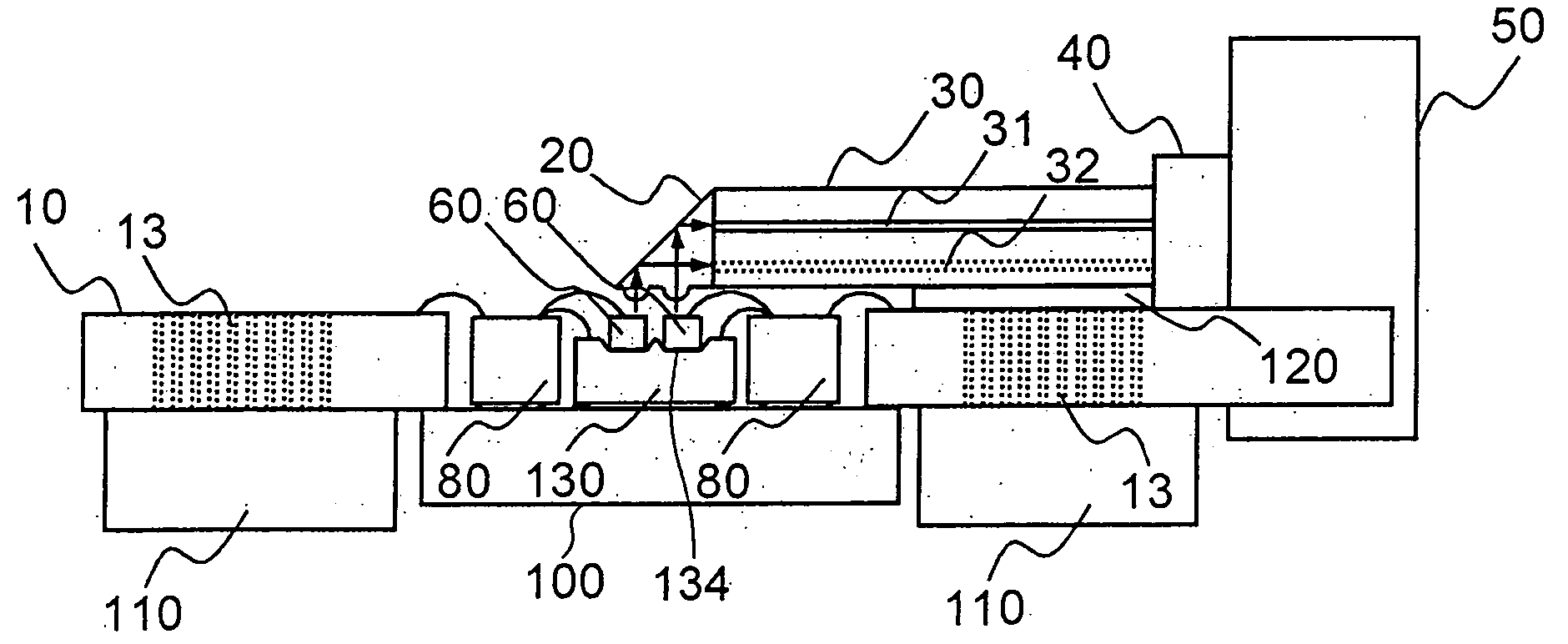
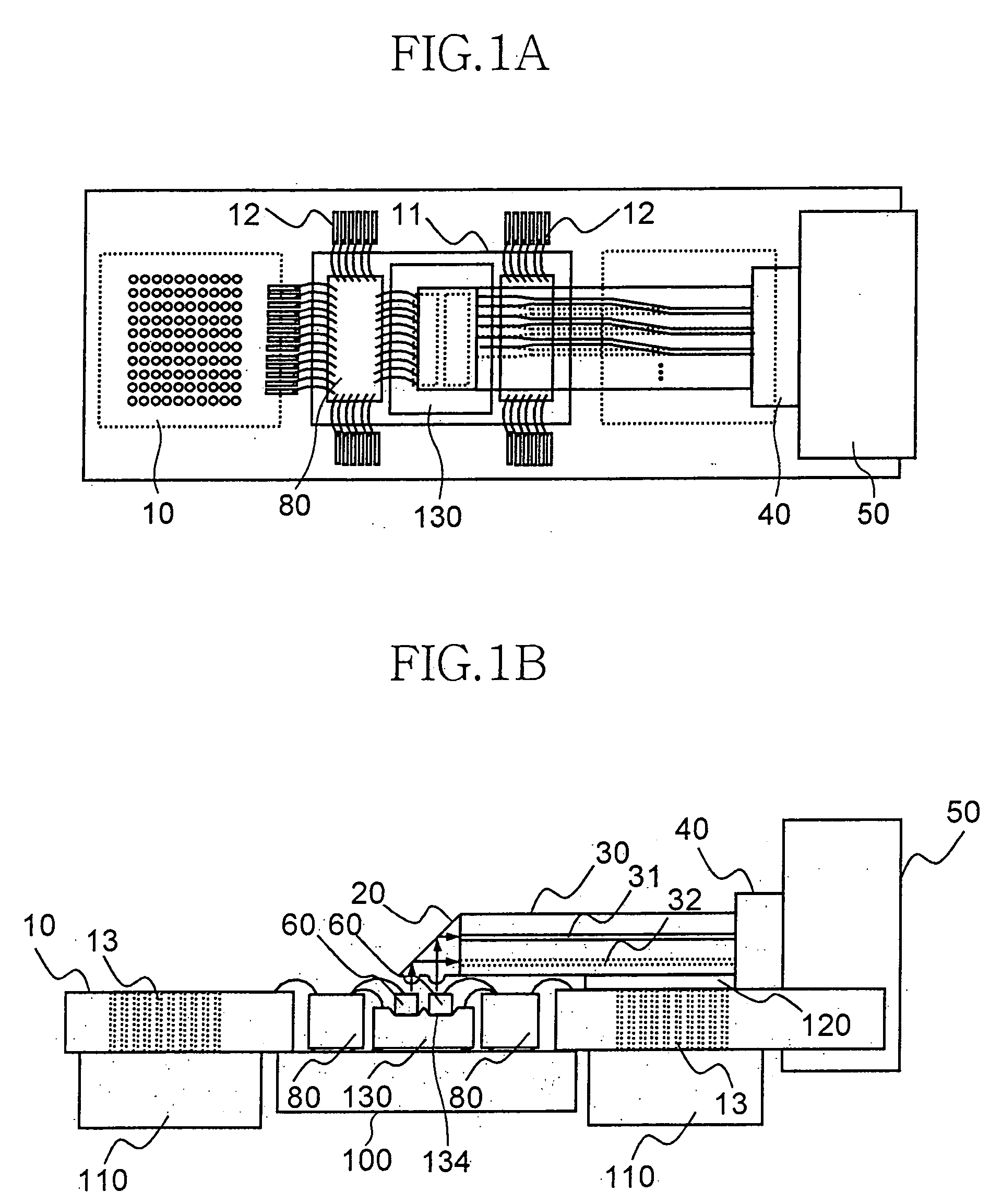
[0031]FIGS. 1A and 1B ...


PUM


Abstract

Provided is an optical connection apparatus for a parallel optical interconnect module and a parallel optical interconnect module using the same for reducing a coupling loss generated due to an alignment error when coupled with an optical fiber, comprising: a 2D reflector in a prism shape and having at least two rows of cylinder type lens attached thereto; a 2D optical waveguide having at least two layers of core arrays; at least two rows of 2D optical benches; and a 2D ferrule capable of loading at least two layers of optical fibers so as to facilitate the fixing of the 2D optical waveguide for optical interconnection.

Description

BACKGROUND [0001] 1. Field of the Invention [0002] The present invention generally relates to a connection apparatus for a parallel optical interconnect module and a parallel optical interconnect module that an optical signal is transmitted or received through an optical fiber, and more particularly, to a connection apparatus for a parallel optical interconnect module and a parallel optical interconnect module, comprising a 2D reflector with a prism reflecting surface having at least two rows of cylinder type lenses so as to reduce a coupling loss generated from a misalignment when coupled with optical fiber, a 2D optical waveguide having at least two layers of core array, at least two rows of 2D silicon optical benches to reduce a coupling loss generated from a misalignment when coupled with optical fiber, a 2D ferrule for loading at least two layers of optical fibers to facilitate the fixing of the 2D optical waveguide for optical coupling. [0003] 2. Discussion of Related Art [000...

Claims


Application Information

Patent Timeline
IPC IPC(8): G02B6/42
CPCG02B6/4204G02B6/4214G02B6/4249H01L2224/48091H01L2224/48137H01L2224/49175H01L2924/3011H01L2924/00014H01L2924/00H01L2924/30111G02B6/42
Inventor HAN, SANG PILCHO, IN KUIKEE, CHUL SIKAHN, SEUNG HOSUNG, HEE KYUNG
Owner ELECTRONICS & TELECOMM RES INST
Why Eureka
Try Eureka