Slotted tail rotor blade pitch horn and replacement method
- Summary
- Abstract
- Description
- Claims
- Application Information
AI Technical Summary
Benefits of technology
Problems solved by technology
Method used
Image

Examples
Embodiment Construction
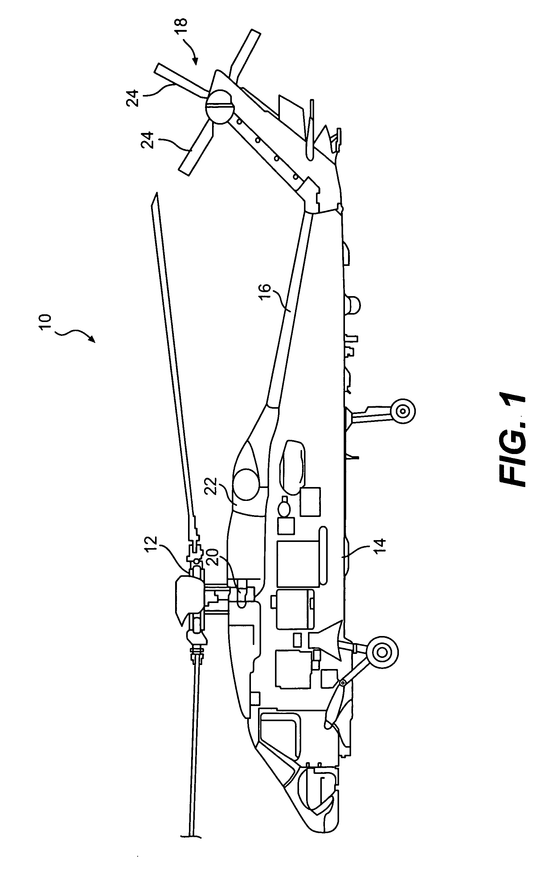
[0037]FIG. 1 schematically illustrates a rotary-wing aircraft 10 having a main rotor assembly 12. The aircraft 10 includes an airframe 14 having an extending tail 16 which mounts an anti-torque tail rotor system 18. The main rotor assembly 12 is driven through a transmission (illustrated schematically at 20) by one or more engines 22. Although a particular helicopter configuration is illustrated in the disclosed embodiment, other machines such as turbo-props, tilt-rotor and tilt-wing aircraft will also benefit from the present invention.
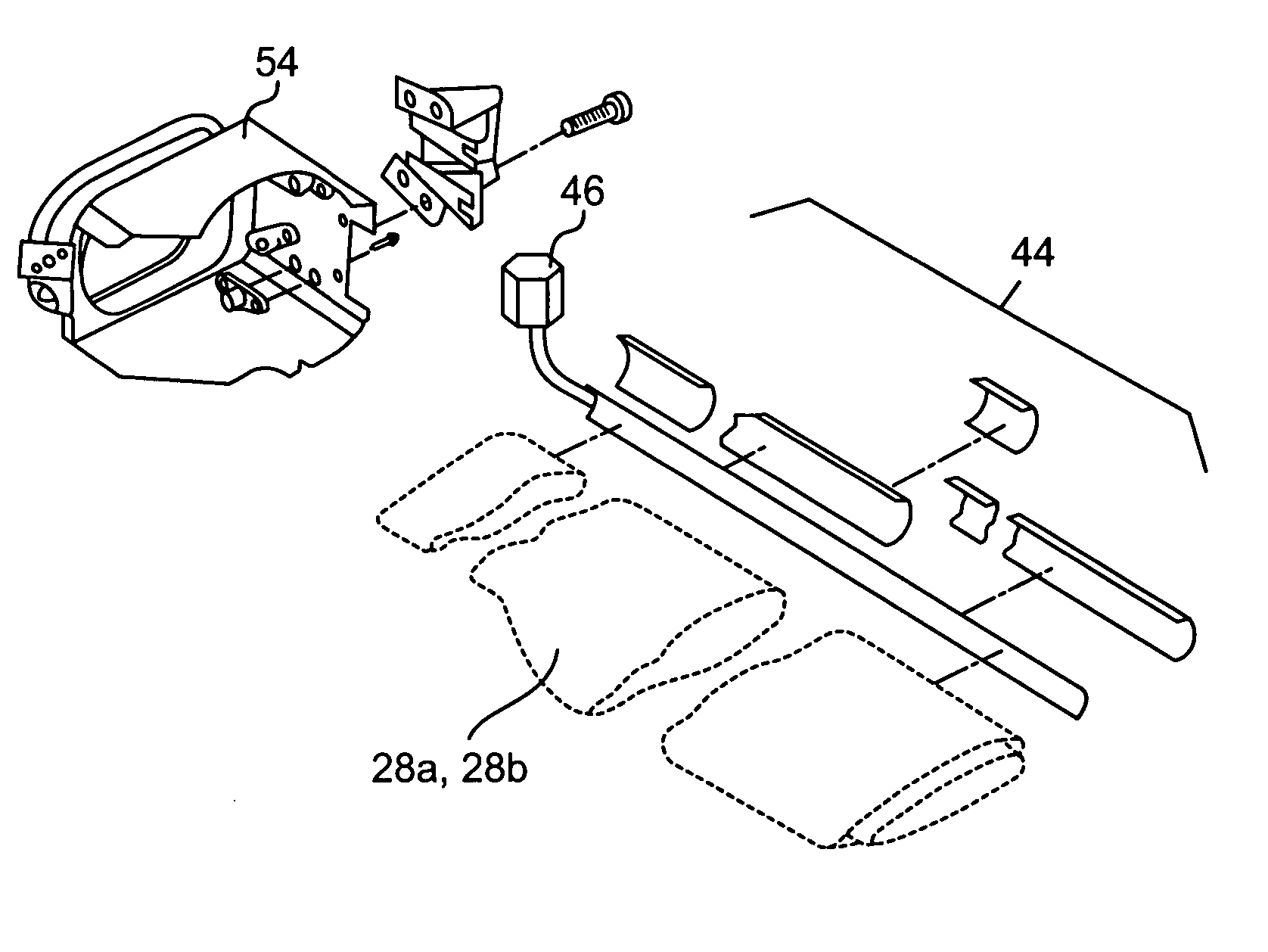
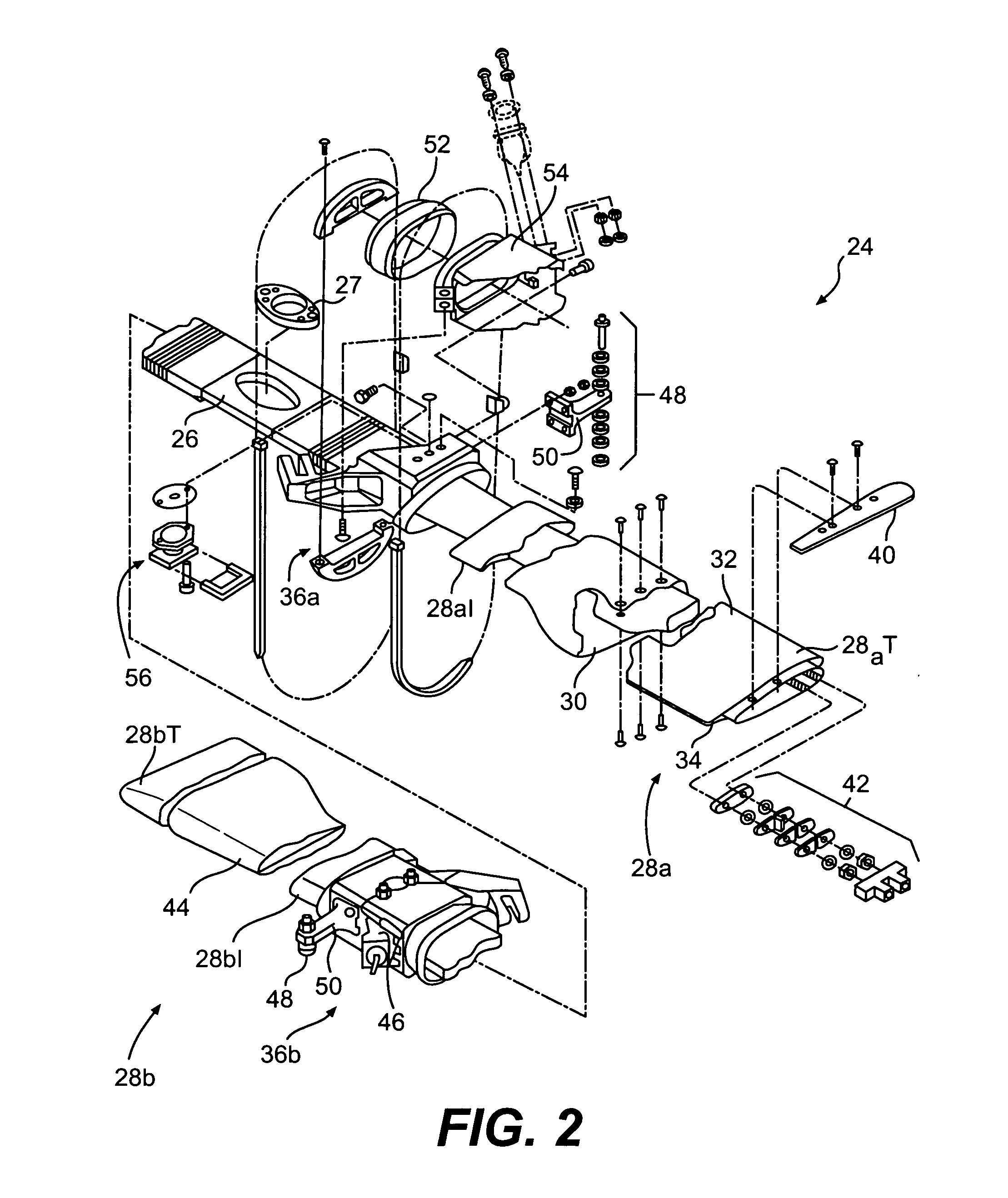
[0038] Referring to FIG. 2, one tail rotor assembly 24 of the tail rotor system 18 is illustrated. The tail rotor assembly 24 is preferably a cross-beam tail rotor system which includes a spar 26 that accommodates blade flap and pitch change motion by deflection. Typically, two tail rotor assemblies 24 will be mounted transverse each other upon a single axle (FIG. 1) through a central mount aperture 27 located through the spar 26 of each tail rotor ...
PUM
| Property | Measurement | Unit |
|---|---|---|
| Width | aaaaa | aaaaa |
| Surface | aaaaa | aaaaa |
Abstract
Description
Claims
Application Information
 - R&D Engineer
- R&D Manager
- IP Professional
- Industry Leading Data Capabilities
- Powerful AI technology
- Patent DNA Extraction
Browse by: Latest US Patents, China's latest patents, Technical Efficacy Thesaurus, Application Domain, Technology Topic.
© 2024 PatSnap. All rights reserved.Legal|Privacy policy|Modern Slavery Act Transparency Statement|Sitemap