Methods and compositions related to a matrix chip

a matrix chip and matrix technology, applied in the field of cell biology and cancer diagnosis, can solve the problems of limited use of cell morphology for cancer detection, unrecognized clinical use, and insufficient routine clinical use, and achieve the effect of realistic assessment of the efficacy of anti-cancer agents, modulating the phenotype of cells, and reducing the probability of metastasis

Inactive Publication Date: 2005-06-30
BOARD OF TRUSTEES OF THE UNIV OF ILLINOI THE +1
View PDF6 Cites 3 Cited by
  • Summary
  • Abstract
  • Description
  • Claims
  • Application Information

AI Technical Summary

Benefits of technology

[0026] In still further embodiments of the invention, cells are grown on thin and thick matrix, or gradients thereof, using devices and methods of the invention. The cells grown on thin and thick matrix are harvested separately. Harvesting is preferably performed mechanically in order to avoid artifacts that may accompany the use of chemical methods such as treatment with chelating agents such as EDTA or EGTA or with proteolytic enzymes such as trypsin that are commonly employed for this purpose. The cells harvested from thin and thick matrix are then separately prepared for application to “gene array” chips such as an Affymetrix II Microarray (Affymetrix). The data obtained from these chips is then analyzed, preferably using a paired T-test, correlation analyses or similar methods, to identify the specific genes for which expression differs between cells grown on thin and thick matrix. Methods of the invention include the identification of a therapy or therapeutic target for modulating the phenotype of a cell. The phenotype may be a senescent or invasive phenotype. The phenotype desired is based on the therapeutic effect desired, for example an invasive phenotype may be more sensitive to a particular therapy, whereas a senescent phenotype may be resistant to the therapy, but the probability of metastasis is decreased. Minimizing metastasis may be used in conjunction with surgery or other cancer therapies.
[0027] Embodiments of the invention include additional methods for use in analysis of standardized panels of tumor tissues and / or cells against which the efficacy of potential anti-cancer agents can be assessed. Some such panels are comprised of living tissues excised from patient tumors while others are comprised of cultured tumor cells grown on a substrate or in suspension. Improved tumor panels can be constructed by growing tumor cells of the requisite type or types using devices and / methods of the present invention. In certain aspects, the tumor panels are more representative of the environments in which in vivo tumor growth occurs and therefore provide for more realistic assessment of the efficacy of anti-cancer agents. These improved panels provide a more defined and controlled environment than do panels comprised of tumor tissues and therefore facilitate comparative assessments. Invasive tumor cells grown on thin matrix are typically more susceptible to the action of anti-cancer agents than are the same cells grown on thick matrix. Thus the apparent efficacy of agents tested against invasive cells grown on thin matrix will be artifactually elevated. Conversely, the invasive behavior of tumors grown on thick matrix can be less than that of the same cells grown on thin matrix. This can mask the efficacy of the agent being tested. More accurate testing can be performed if cells grown on both thin and thick matrix are employed as reference materials in the manner embodied in this invention.

Problems solved by technology

Proteomic techniques that identify cancer cells by evaluating changes in the expression of large suites of proteins are under development, but are not yet in routine clinical use.
The primary limitation on the use of cell morphology for cancer detection largely derives from the low signal to noise ratio (SNR) that is inherent in this process.
Despite such training and numerous attempts to systematize the evaluation of cell morphology, it is still often difficult to reach a consensus as to whether a particular cell is actually cancerous and, if so, the type of cancer it represents and its prognosis.
As may be expected, this subjectivity also imposes significant limitations on the performance of automated systems for the evaluation of cell morphology.
Both methods, however, are known to be impacted by biological noise and, as a consequence, are used in conjunction with morphological analysis in order to obtain a definitive determination.
Such highly sensitive tests intrinsically generate a high level of false positive results, each of which requires extensive and expensive follow-up and, therefore, represents a significant waste of health care resources.

Method used


Image

  • Methods and compositions related to a matrix chip
  • Methods and compositions related to a matrix chip
  • Methods and compositions related to a matrix chip

Examples


example 1

Device Fabrication—Discrete Heights

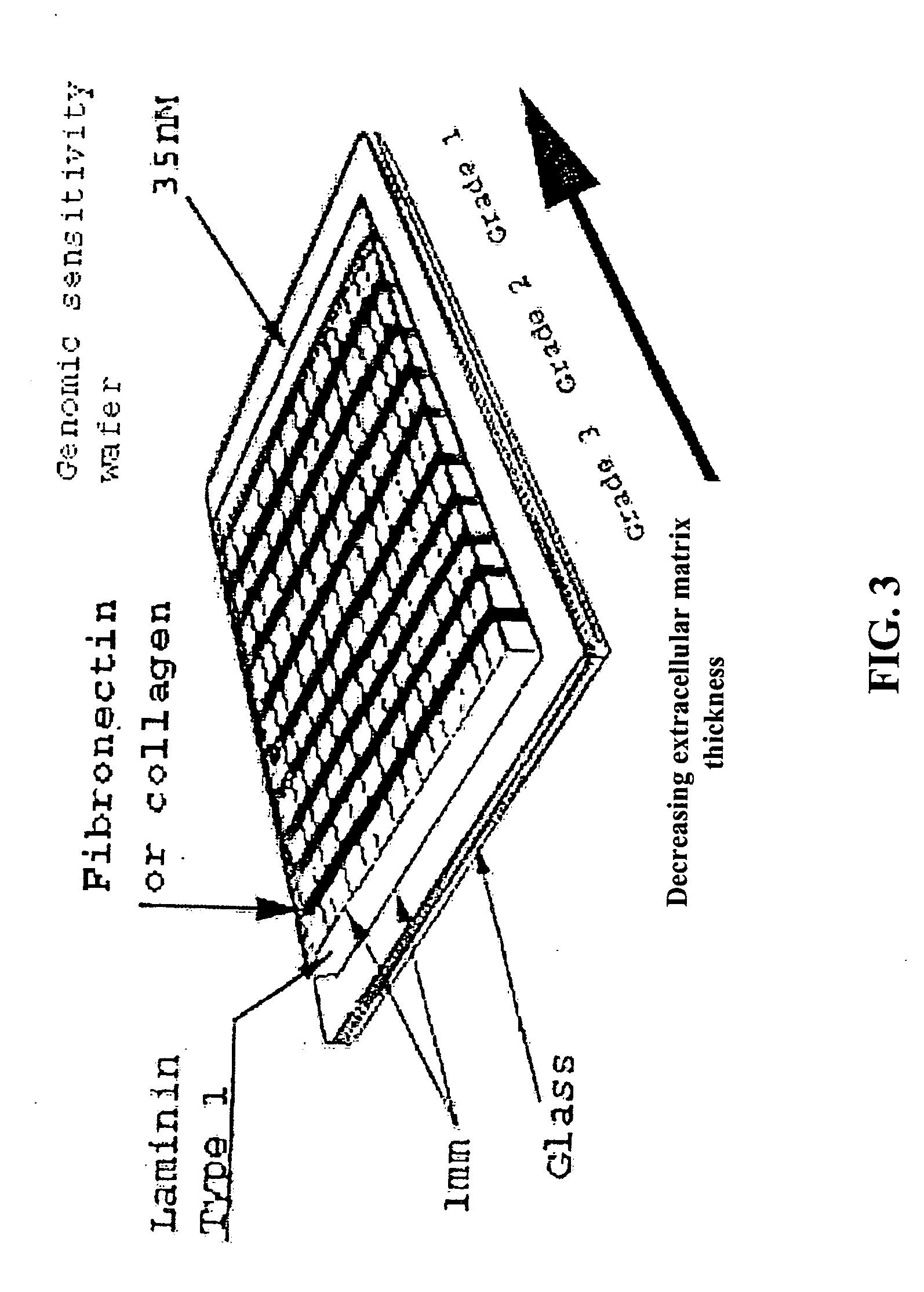
[0090] A device suitable for the practice of this invention may consist of one or more regions or zones of material of defined composition and thickness that is deposited or formed upon or within a substrate. In certain embodiments, such devices include multiple regions or zones of material deposited or formed upon or within a substrate. Each region may have the same or different composition and / or thickness as one or more other regions of material on the same substrate. In some instances it is desirable for the region(s) to abut one another. In other instances it is desirable for the regions to be spaced apart or divided by a barrier.

[0091] An example of such a process includes, but is not limited to a mask created using SU-8 / 250 negative resist (Microlithography Chemical Co.) that can be prepared as follows. Suitably cleaned substrates are dehydrated at 200° C. for 1 hr and cooled to room temperature in a dry atmosphere. The substrate is then m...

example 2

Device Fabrication—Gradient

[0092] In some instances it is convenient or desirable that the thickness of the matrix protein within a zone vary in a continuous manner between some minimum and maximum values. This is most conveniently accomplished by forming the zones of matrix on the surface of the substrate in accordance with any of the damascene procedures described above, but modifying the procedure such that the substrate is supported at an angle relative to the horizontal that is calculated to result in the desired thickness gradient during the denaturation baking step of the process. Alternatively, the desired thickness gradient can be formed into the substrate by casting, molding, embossing, engraving, etch; or hot stamping prior to applying the matrix protein.

example 3

Determination of Cellular Invasiveness

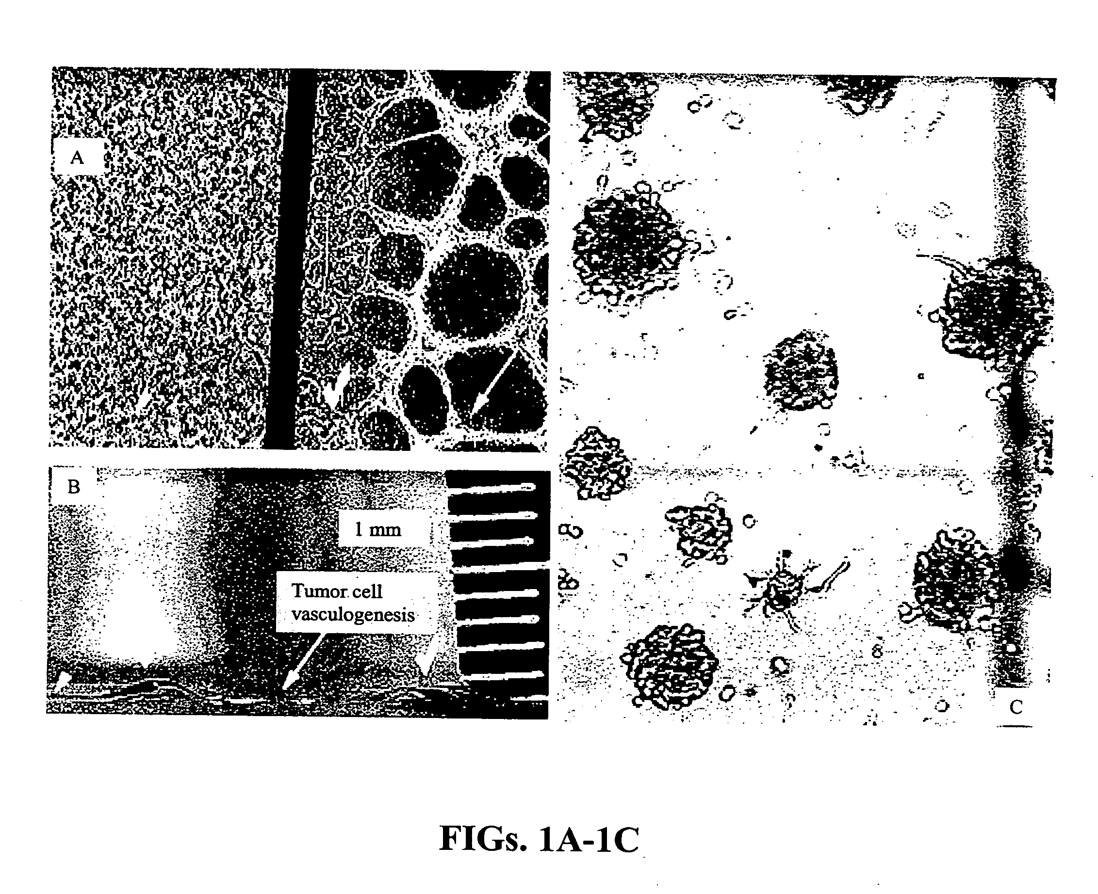
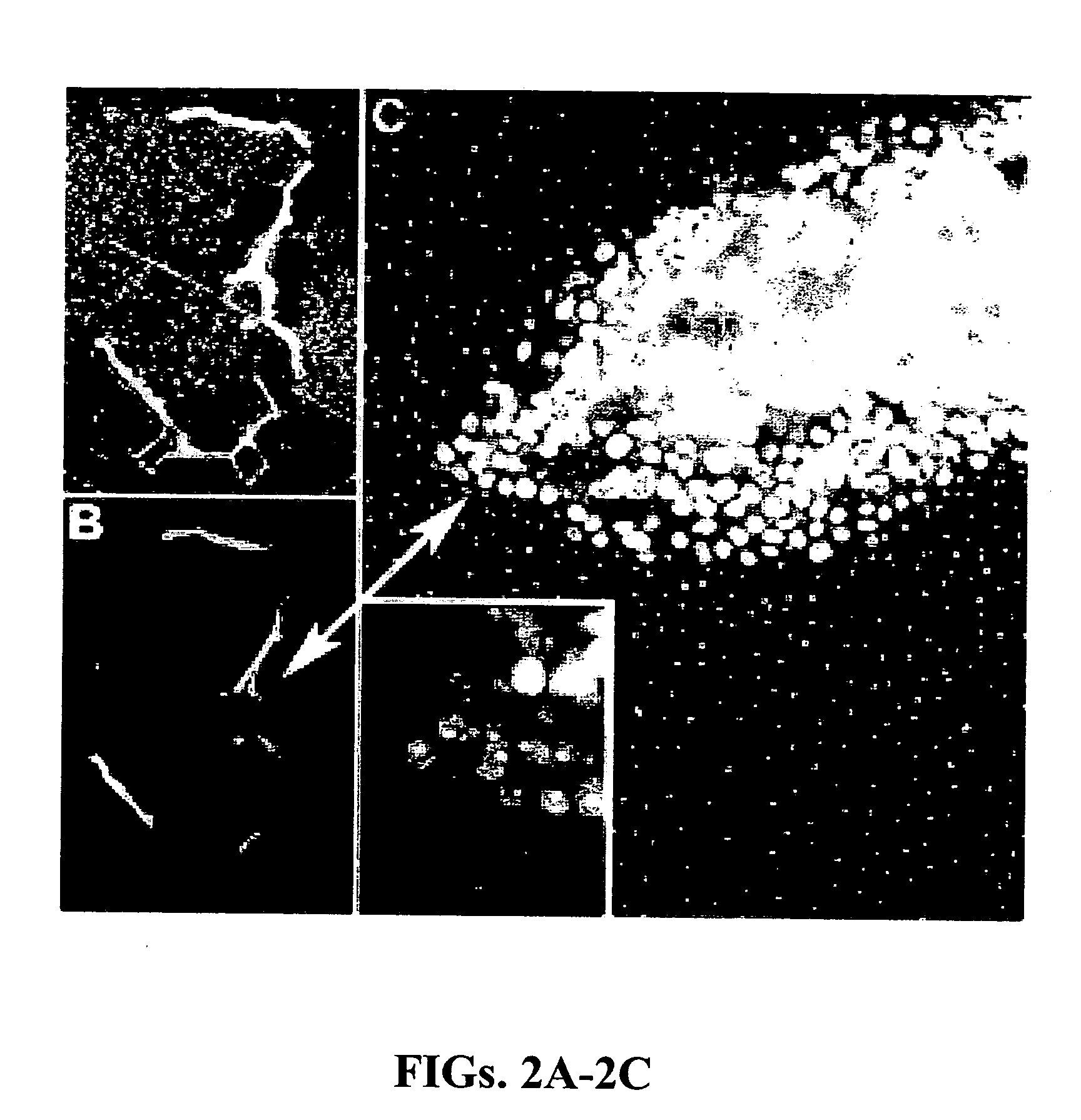
[0093] A device consisting of two sets of two parallel lines of collagen matrix protein, each line being 10 microns by 100 microns in extent on 100 micron centers, was fabricated on a glass microscope coverslip by casting each line in an opening in a silicone rubber mask as described above. The thickness of the matrix material comprising each line was controlled by adjusting the amount of matrix protein solution dispensed into an opening in the mask. The two sets of parallel lines had matrix protein thicknesses of approximately 30 microns (thin matrix) and 200 microns (thick matrix), respectively, after annealing at 55° C. for one hour. After removal of the mask, the coverslip with inscribed lines of matrix protein was placed on the bottom of a plastic cell culture dish and covered with approximately 30 mL of DMEM cell culture medium supplemented with 10% fetal calf serum. A micropipette was used to seed one line in each set with non-invasive O...


PUM

PropertyMeasurementUnit
thicknessaaaaaaaaaa
thicknessaaaaaaaaaa
thicknessaaaaaaaaaa

Abstract

Embodiments of the invention relate to devices and methods for evaluating the interactions between cells and between cells and matrix materials wherein the cellular distribution patterns formed as a result of such interactions are indicators of the invasive potential(s) of the cells. Furthermore, such devices and methods can provide indications of the preferred sites of metastasis of invasive cells; the efficacy of an anti-cancer drug applied to such cells; and the potential for agents to promote or enhance tumor growth or metastasis.

Description

[0001] This application claims priority to U.S. Provisional Patent applications Ser. Nos. 60 / 511,543, filed Oct. 14, 2003; 60 / 526,792, filed Dec. 4, 2003; and 60 / 574,437, filed May 26, 2004; which are incorporated herein by reference in their entirety.[0002] The government may own rights in the present invention pursuant to grant number ROI EY 10457 from the National Institutes of Health and grant number W-7405-ENG-48 from the Department of Energy.BACKGROUND [0003] 1. Field of the Invention [0004] The invention relates generally to cell biology and cancer diagnosis. In particular, the invention relates to compositions, methods, and devices for detecting invasive mammalian cells, for differentiating between degrees of invasiveness of cells and for identifying compounds that regulate the invasiveness of cells. [0005] 2. Description of Related Art [0006] Numerous methods have been devised for the detection of cancer. These range from the imaging of tumor masses by X-ray and optical tec...

Claims


Application Information

Patent Timeline
Patent Type & Authority Applications(United States)
IPC IPC(8): A01N1/00C12NC12Q1/68
CPCC12N5/0068C12N2533/52C12N2533/54C12N2533/90G01N2500/10G01N33/5017G01N33/5091G01N33/574G01N33/5011A61P35/00A61P35/04
Inventor MANIOTIS, ANDREW J.FOLBERG, ROBERT
Owner BOARD OF TRUSTEES OF THE UNIV OF ILLINOI THE
Why Eureka
Try Eureka