Method of treatment of refractive errors using subepithelial or intrastromal corneal inlay with bonding coating

a technology of corneal inlay and bonding coating, which is applied in the field of treating refractive errors, can solve the problems of affecting the recovery of vision, affecting the ability of the cornea to be inserted, so as to achieve the effect of not distorting the farsighted vision

Inactive Publication Date: 2005-06-30
MINU
View PDF55 Cites 44 Cited by
  • Summary
  • Abstract
  • Description
  • Claims
  • Application Information

AI Technical Summary

Benefits of technology

[0014] Accordingly, it is an object of the present invention to provide an improved method for modifying the cornea of an eye, particularly for correcting presbyopia.
[0015] Another object of the present invention is to provide a method for modifying the cornea of an eye that results in a precise separation between layers in the cornea.
[0016] Still another object of the present invention is to provide a method for modifying the cornea of an eye that allows for corrective measures that avoid or eliminate outbulging or instability in the cornea.

Problems solved by technology

However, there can be problems when microkeratomies are used for cutting the cornea.
First, irregular keratectomies or perforations of the eye can result.
Second, the recovery of vision can be rather prolonged.
By separating the layers in the bottom two-thirds of the stromal, it is difficult to access the separated area to insert the inlay and virtually impossible to change or modify the inlay without another extensive surgical procedure.
Other conventional methods that have been employed specifically to correct presbyopia have been unsuccessful.
However, because only certain amount of cornea can be ablated without the remaining cornea becoming unstable or experiencing outbulging (ectasia), this technique is not especially effective in correcting very high myopia.
Also, these conventional implants, while correcting a refractive error of the patient, also distort the normal vision of the patient.
Use of these instruments may result in damage or imprecision in the cut or formation of the desired area in which the implant is placed.
Additionally, these conventional techniques do not include determination and testing of an appropriate implant for correcting a refractive error of a particular patient.
Prior methods for the treatment of presbyopia have been unsuccessful.
However, because the disc covered the center area around the visual axis, the patient's farsighted vision was blurred by the inlay.

Method used


Image

  • Method of treatment of refractive errors using subepithelial or intrastromal corneal inlay with bonding coating
  • Method of treatment of refractive errors using subepithelial or intrastromal corneal inlay with bonding coating
  • Method of treatment of refractive errors using subepithelial or intrastromal corneal inlay with bonding coating

Examples


Embodiment Construction

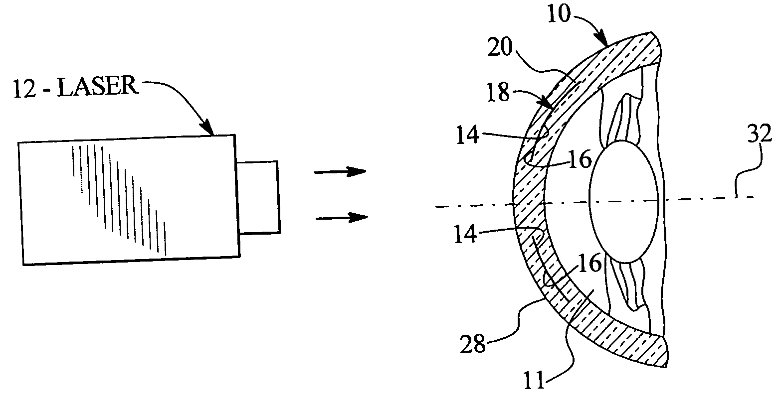
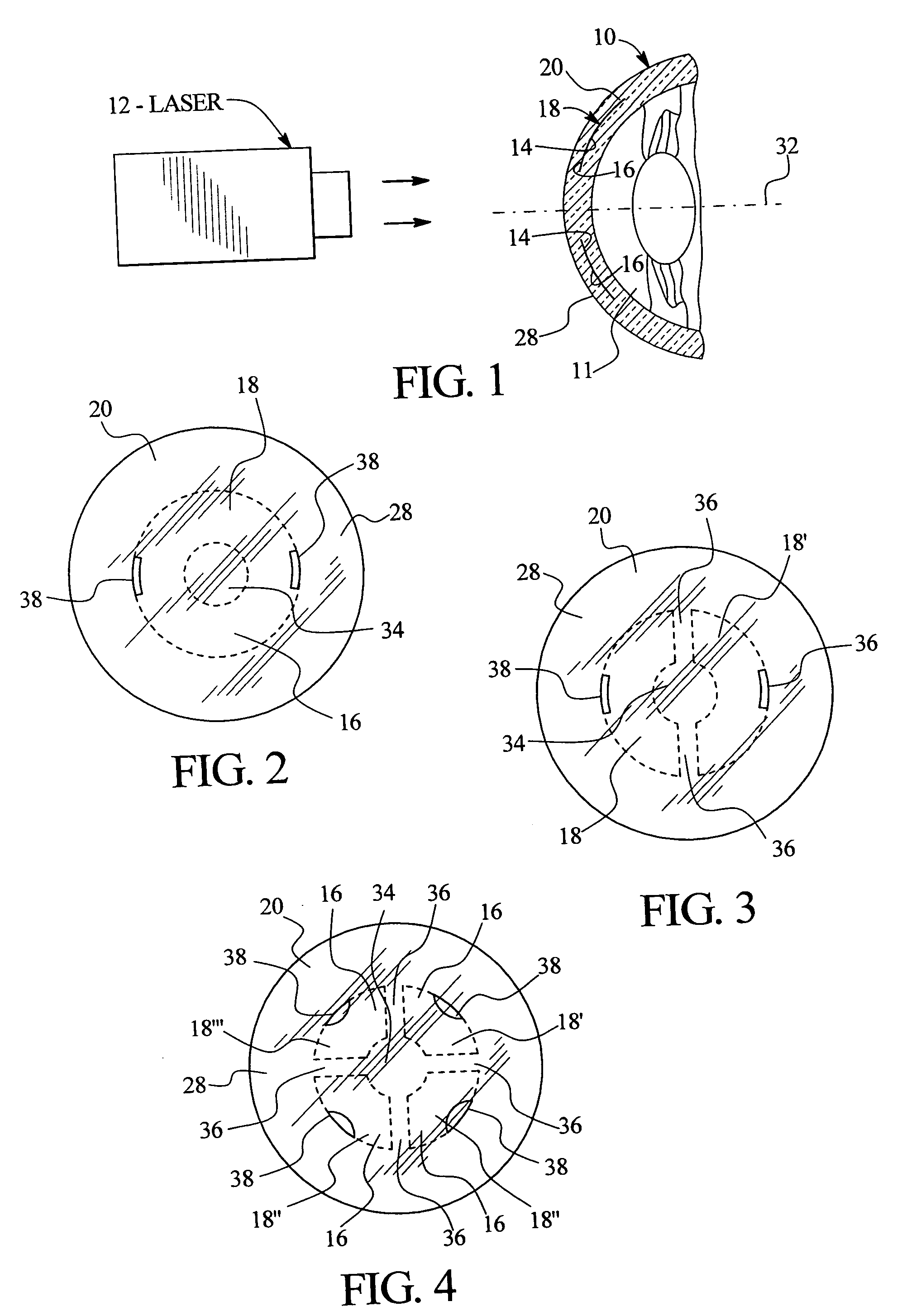
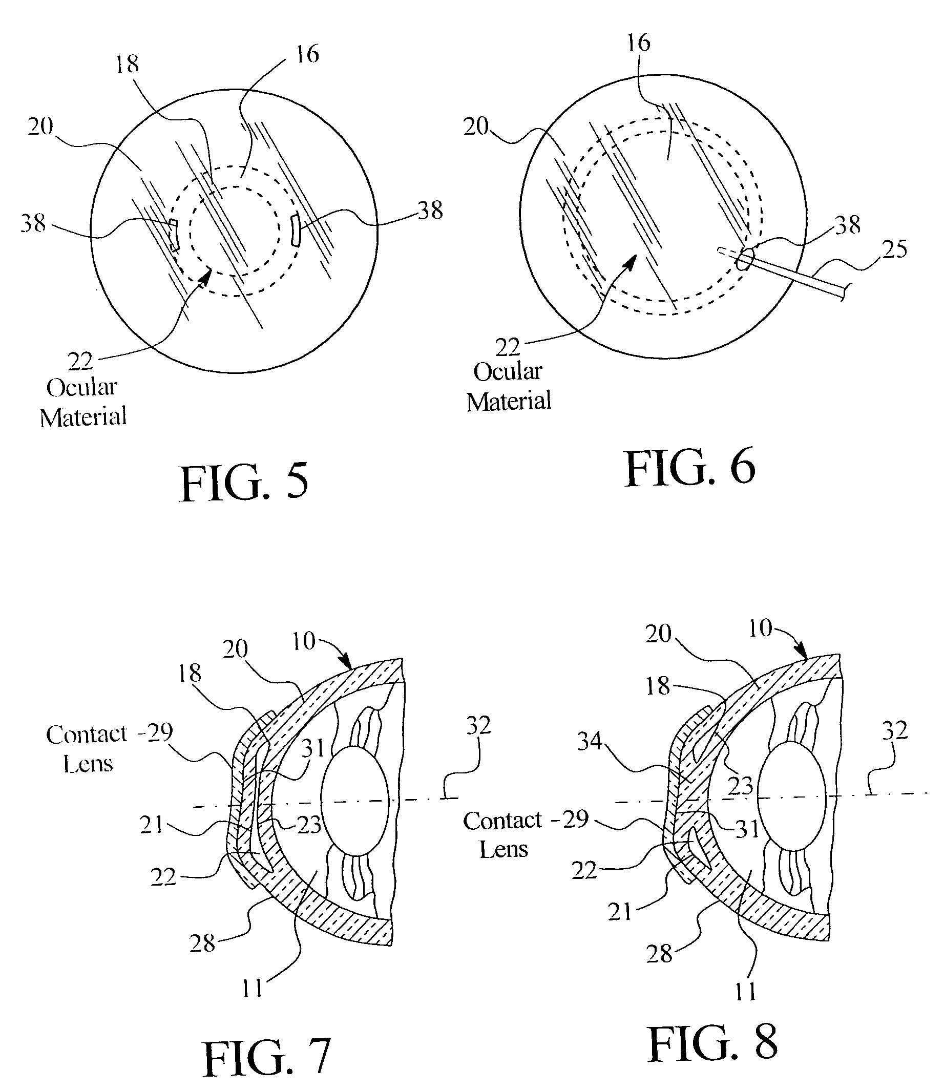
[0115] As initially shown in FIGS. 1, 2 and 19-24, the refractive properties of eye 10 can be altered by using laser 12 to separate an inner portion of the cornea into first internal corneal surface 14 and second internal corneal surface 16, creating internal corneal pocket 18 in the cornea 20 and then placing ocular material or an implant 22 in the pocket 18. Additionally, the cornea can be shaped by using a second laser 24 to ablate a portion 26 of the surface 28 of the cornea 16, or an external lens 29 to mold the ocular material.

[0116] To begin, the refractive error in the eye is measured using wavefront technology, as is known to one of ordinary skill in the art. For a more complete description of wavefront technology see U.S. Pat. No. 6,086,204 to Magnate, the entire contents of which is incorporated herein by reference. The refractive error measurements are transmitted to a computerized lathe (not shown) or other lens-shaping machine, where the shape of ocular material is de...


PUM


Abstract

A method of treatment of refractive errors of an eye, the eye including a central visual axis and a cornea with a first corneal layer overlying a second corneal layer, comprising the steps of separating a first surface of the first corneal layer from a second surface of the second corneal layer, thereby forming a flap and exposing the second surface, implanting on the second surface an inlay adapted to correct a refractive error of the eye, coating a surface of the inlay with a compound that promotes bonding with the cornea, and replacing the flap over the inlay.

Description

RELATED APPLICATIONS [0001] This application is a continuation-in-part of U.S. patent application Ser. No. 10 / 406,558, filed Apr. 4, 2003 which claims the benefit of U.S. Provisional Application Ser. No. 60 / 449,617, filed Feb. 26, 2003, and is a continuation-in-part of U.S. patent application Ser. No. 10 / 356,730, filed Feb. 3, 2002 which is a continuation-in-part of U.S. patent application Ser. No. 09 / 843,141, filed Apr. 27, 2001, the entire contents of each of which are herein incorporated by reference.FIELD OF THE INVENTION [0002] The present invention relates to a method for treating refractive errors of a patient's eye. More specifically, an inlay is selected for correcting the patient's refractive error, implanted, and immobilized in proper position on the patient's cornea using a bonding compound, such as an organic coating. BACKGROUND OF THE INVENTION [0003] Conventional methods of treating refractive errors involve implanting a corrective lens by removing a portion or flap o...

Claims


Application Information

Patent Timeline
Patent Type & Authority Applications(United States)
IPC IPC(8): A61B17/24A61B18/18A61F9/00A61F9/008A61F9/01A61F9/013
CPCA61F9/0017A61F9/008A61F9/00808A61F9/00812A61F2009/0088A61F9/00836A61F9/013A61F2009/00872A61F9/00819
Inventor PEYMAN, GHOLAM A.
Owner MINU
Why Eureka
Try Eureka