Data transfer method and system

Inactive Publication Date: 2005-06-30
HITACHI LTD
View PDF11 Cites 29 Cited by
  • Summary
  • Abstract
  • Description
  • Claims
  • Application Information

AI Technical Summary

Benefits of technology

[0012] One of the concepts of the present invention is that block-basis data transfer and file-basis data transfer can be switched, as necessary, for transferring data from one storage unit (for example, storage, disk, volume, storage area) to another. Another concept is that two types of transfer technology can be used as necessary: a transfer technology used in a system that manages data, stored in a storage unit, at a block level and a transfer technology used in a system that manages data at a file level. This makes it possible to realize a more flexible data transfer with no limitation of a single-protocol data transfer. In addition, the user can select from a wider range of networks according to various data transfer conditions and status (user needs, network usage status, etc.).
[0013] More specifically, the present invention provides a computer system that transfers data from a first storage unit to a second storage unit via a network (for example, SAN, LAN, WAN). The computer system comprises a first controller that transfers data, stored in the first storage unit, to the second storage unit on a block basis using a block transfer protocol; a table (for example, file / block management table) that associates a file composed of a plurality of blocks of data with blocks of data constituting the file; and a second controller that, in response to information that identifies a block (for example, logical block address) from the first controller, identifies a file corresponding to the block using the table and transfers the identified file to the second storage unit on a file basis using a file transfer protocol. The first controller and the second controller may reside in a storage system and a server with the file management function, respectively, as in a SAN configuration or may reside in the same system / cabinet as in a NAS (Network Attached Storage) configuration. Data may be transferred via a plurality of networks to flexibly perform processing for a network failure or to utilize the network characteristics (both a relatively high speed, high reliability, high cost network and a relatively low speed, low reliability, low cost network are used); for example, data under the block transfer protocol is transferred in a SAN where resources are connected via fibre channels and data under the file transfer protocol is transferred in a LAN.
[0014] When the transfer of data from the first storage unit using the block transfer protocol fails, for example, when a failure is detected at the time data is read from the first storage unit or a transfer processing failure including a network failure is detected (is judged as a failure) or when a data reception rejection is received from the system managing the second storage unit, the first controller may notify the information, which identifies the transfer-failed block, to the second controller. This allow data transfer processing to be switched at a predetermined time such as a user specified time and, in particular, assures data transfer processing when the data transfer processing fails.
[0017] The first storage unit comprises at least a main volume and a sub volume. When the block-basis transfer of data from the sub volume fails, the first controller notifies information, which identities the transfer-failed data block, to the second controller and, in response to an instruction to transfer a plurality of blocks of data related to the transfer-failed file from the second controller, transfers data stored on the main volume and corresponding to the plurality of blocks on a block basis. This makes it possible to use a data processing method that minimizes the effect on the processing that is executed usually using the main volume.

Problems solved by technology

When the transfer of data from the first storage unit using the block transfer protocol fails, for example, when a failure is detected at the time data is read from the first storage unit or a transfer processing failure including a network failure is detected (is judged as a failure) or when a data reception rejection is received from the system managing the second storage unit, the first controller may notify the information, which identifies the transfer-failed block, to the second controller.

Method used


Image

  • Data transfer method and system
  • Data transfer method and system
  • Data transfer method and system

Examples


Embodiment Construction

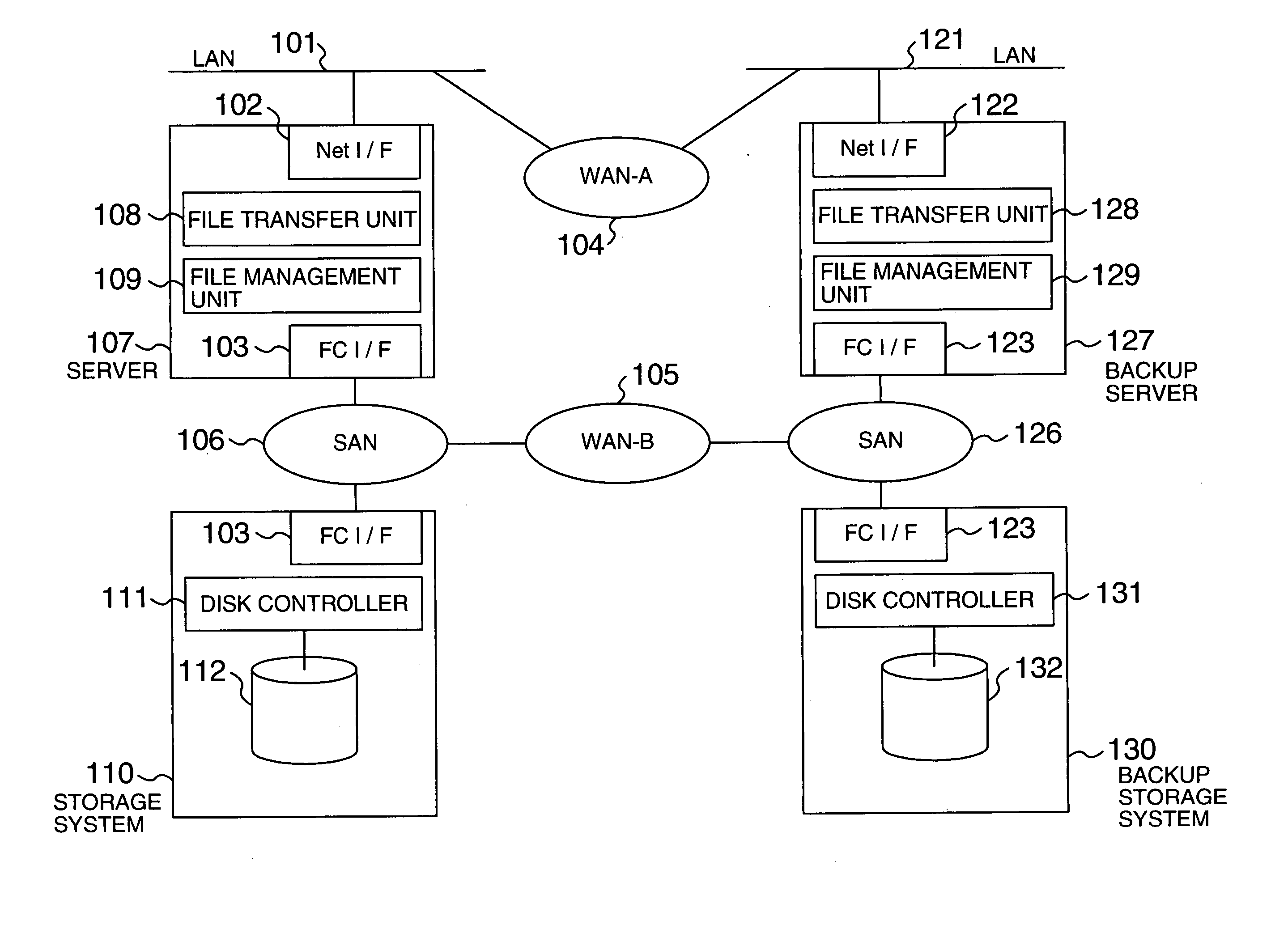
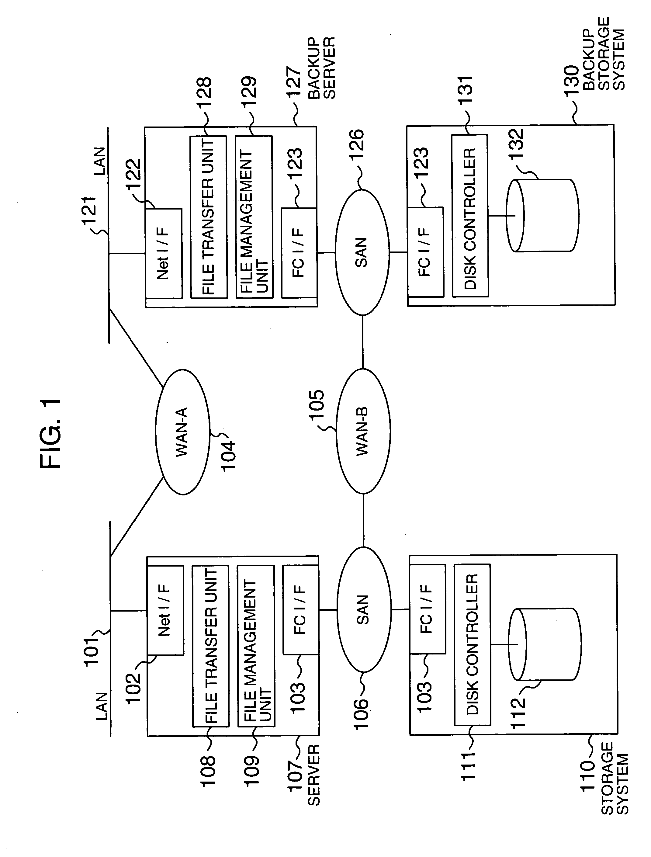
[0032] An embodiment of the present invention will be described in detail with reference to the drawings. FIG. 1 is an overall configuration diagram showing one embodiment of a network environment to which the present invention is applied.

[0033] In this embodiment, a data transfer method according to the present invention is applied to a system where data backup processing is performed. A primary storage system 110 and a primary server 107 are connected to a SAN 106 via a fibre channel interface (FC I / F) 103. The server 107 comprises a controller such as a microchip that controls the whole system and performs program processing and a storage unit in which programs and data are stored. The storage unit, composed of a main storage unit such as a memory, an auxiliary storage unit such as a hard disk, and a database, stores an OS (Operating System), a file transfer program, a file management program, application programs, as well as data and programs necessary for processing executed o...


PUM


Abstract

A computer system that transfers data from a first storage unit to a second storage unit via a network. The computer system includes a first controller that transfers data, stored in the first storage unit, to the second storage unit using a block transfer protocol; a table that associates a file composed of a plurality of blocks of data with blocks of data constituting the file; and a second controller that, in response to information that identifies a block from the first controller, identifies a file corresponding to the block using the table and transfers the identified file to the second storage unit using a file transfer protocol.

Description

BACKGROUND OF THE INVENTION [0001] The present invention relates to a technology for transferring data stored in a computer system such as the one used as a storage system, and more particularly to a technology for transferring data, stored in a storage system, to a backup system using NAS (Network Attached Storage) and other file system functions. [0002] Today, as the environment of a network such as the Internet evolves and as digital information becomes more diversified (document, drawing, image, visual content, etc.), an information processing system must processes more and more data. The functions of an information processing system that processes a large amount of data are classified roughly into two: the server function and the storage function. [0003] The server function executes applications in a system, which has the server function, to execute application processing provided by the information processing system. The storage function stores data used by a system that has t...

Claims


Application Information

Patent Timeline
Patent Type & Authority Applications(United States)
IPC IPC(8): G06F3/06G06F13/10G06F11/14G06F12/00G06F13/00G06F15/16H04L29/08
CPCG06F3/0619G06F3/0635G06F3/064G06F3/0643H04L67/1097G06F3/067G06F11/1443G06F11/1464H04L67/06G06F3/065
Inventor KAMEDA, MASAMI
Owner HITACHI LTD
Why Eureka
Try Eureka