
Memory control device and method for controlling the same

a memory control device and memory control technology, applied in the direction of micro-instruction address formation, liquid/fluent solid measurement, instruments, etc., can solve the problems of high cost, high performance and high reliability, and the prior art's technology is not effective for the disk array system or storage control device used for backup, restore, archive, etc., to increase the capacity of data memorized, large capacity of memory

Inactive Publication Date: 2005-06-30
HITACHI LTD
View PDF69 Cites 21 Cited by
  • Summary
  • Abstract
  • Description
  • Claims
  • Application Information

AI Technical Summary

Benefits of technology

[0028] We intend to effect the back-up, restore and archive of data at a high speed in a short period of time in consideration of various elements such as increased capacity of data memorized in the storage control device, variety of kinds thereof and operations around the clock. Therefore, we contemplate the back-up, restore and archive using the storage control device equipped with HDD's as storage mediums for the field in which the back-up and restore of data and archive are carried out by tape drives, as well. In such applications, as large capacity is particularly required, the requirement imposed upon the storage control device is to provide great capacity of memory at much less expensive.

Problems solved by technology

In such applications severe requirements are thus imposed as regards high performance and high reliability.
As the HDD fully complying with the imposed requirements must be highly reliable as one of parts, it would be usually highly expensive.
However, such a technique of the prior art is not effective for the disk array system or storage control device used for the applications such as back-up, restore, archive and the like.

Method used


Image

  • Memory control device and method for controlling the same
  • Memory control device and method for controlling the same
  • Memory control device and method for controlling the same

Examples


second embodiment

[0130] The second embodiment will then be explained.

[0131] There are two different features from the embodiment already explained.

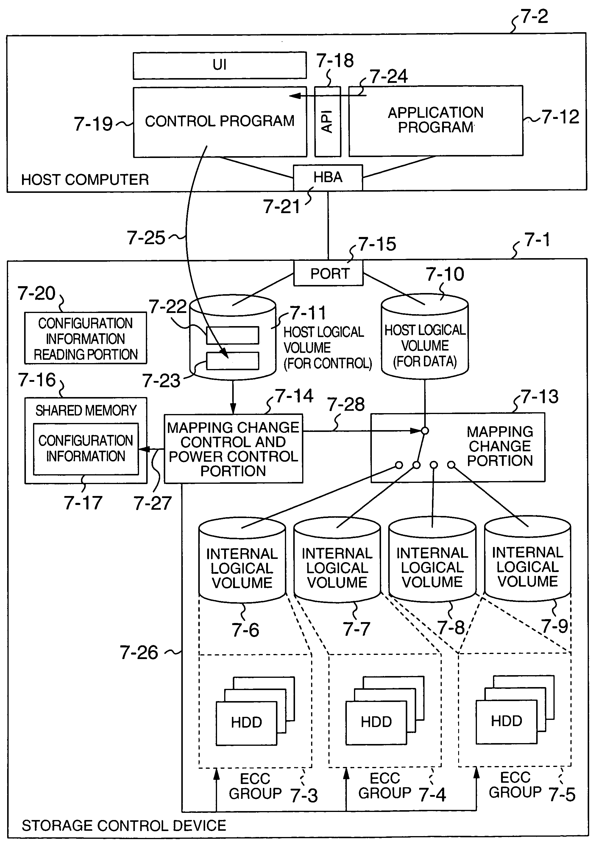
[0132] The first different feature of the present embodiment is no use of the host logical volume (for control) 7-11 as in FIG. 7. Instead of the host logical volume (for control) 7-11, API for control 11-11 provided in the storage control device is used. The API for control 11-11 is provided by the program equipped in the storage control device 11-1. This program is operated in 1) the channel adapter equipped in the storage control device 11-1 or 2) service processor equipped in the storage control device 11-1.

[0133] The second difference of the present embodiment concerns with the transfer path of control information between the storage control device 11-1 and the host computer 11-2. In the embodiment already explained, the control program 7-19 carries out the reading the configuration information and writing the control information with respect to th...

third embodiment

[0135] Next, the third embodiment will be disclosed.

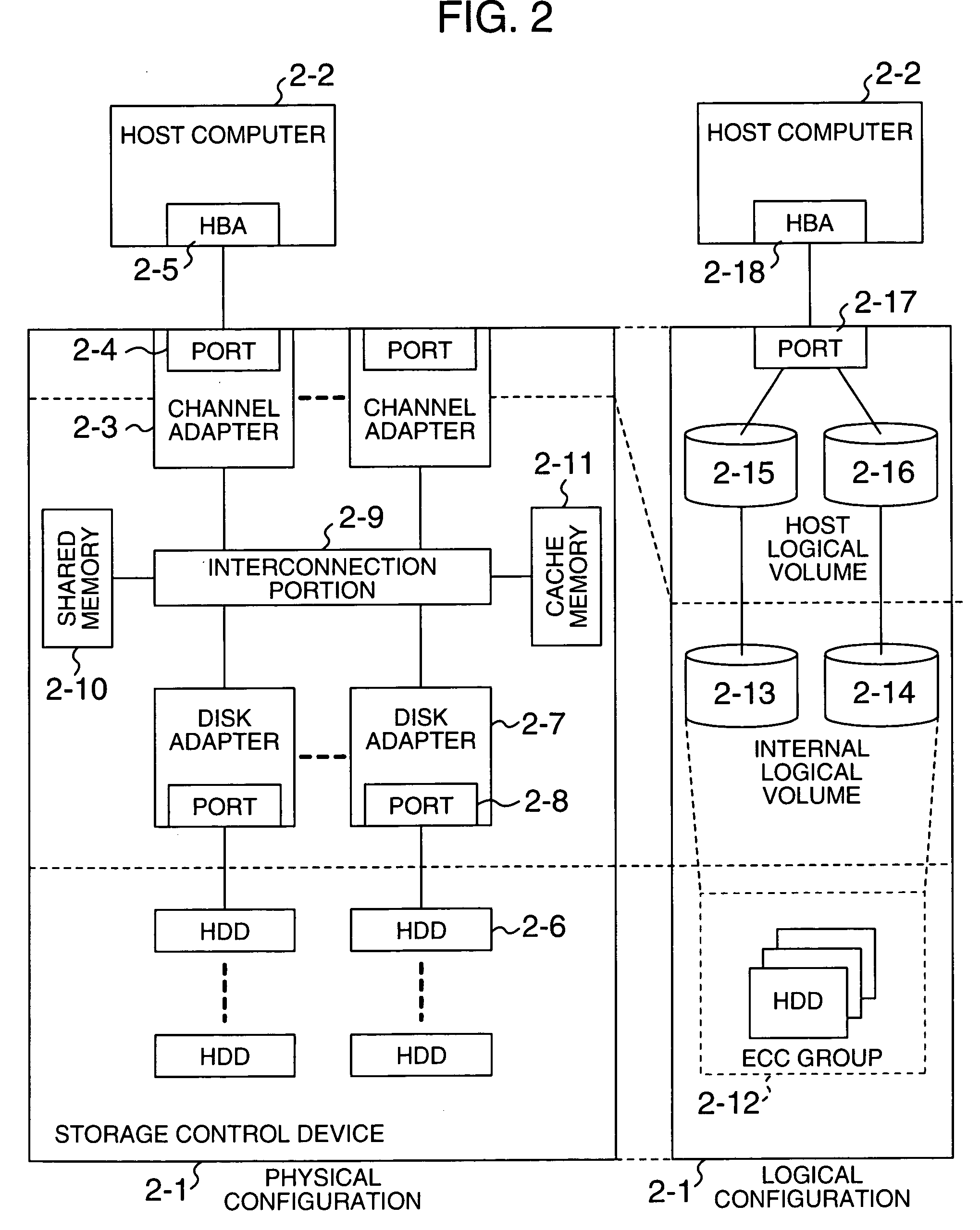
[0136] In the embodiments already explained, a plurality of the HDD are divided into the ECC groups as shown at ECC group 2-12 in FIG. 2 and the memory regions made by the ECC groups are divided into one or plural regions to form the internal logical volumes, and the internal logical volumes are brought into mapping relation to the host logical volume. In the present embodiment, one HDD is used instead of the ECC groups without using the internal logical volumes provided by the ECC groups. The memory region made by the one HDD is divided into one or plural regions to form internal logical volumes which are then brought into the mapping relation to the host logical volume.

[0137] The third embodiment is substantially similar to the embodiments already explained with the exception that one HDD is used instead of the ECC groups.

[0138] In either case, the storage control device for storing data to be processed by the host computer is ...


PUM


Abstract

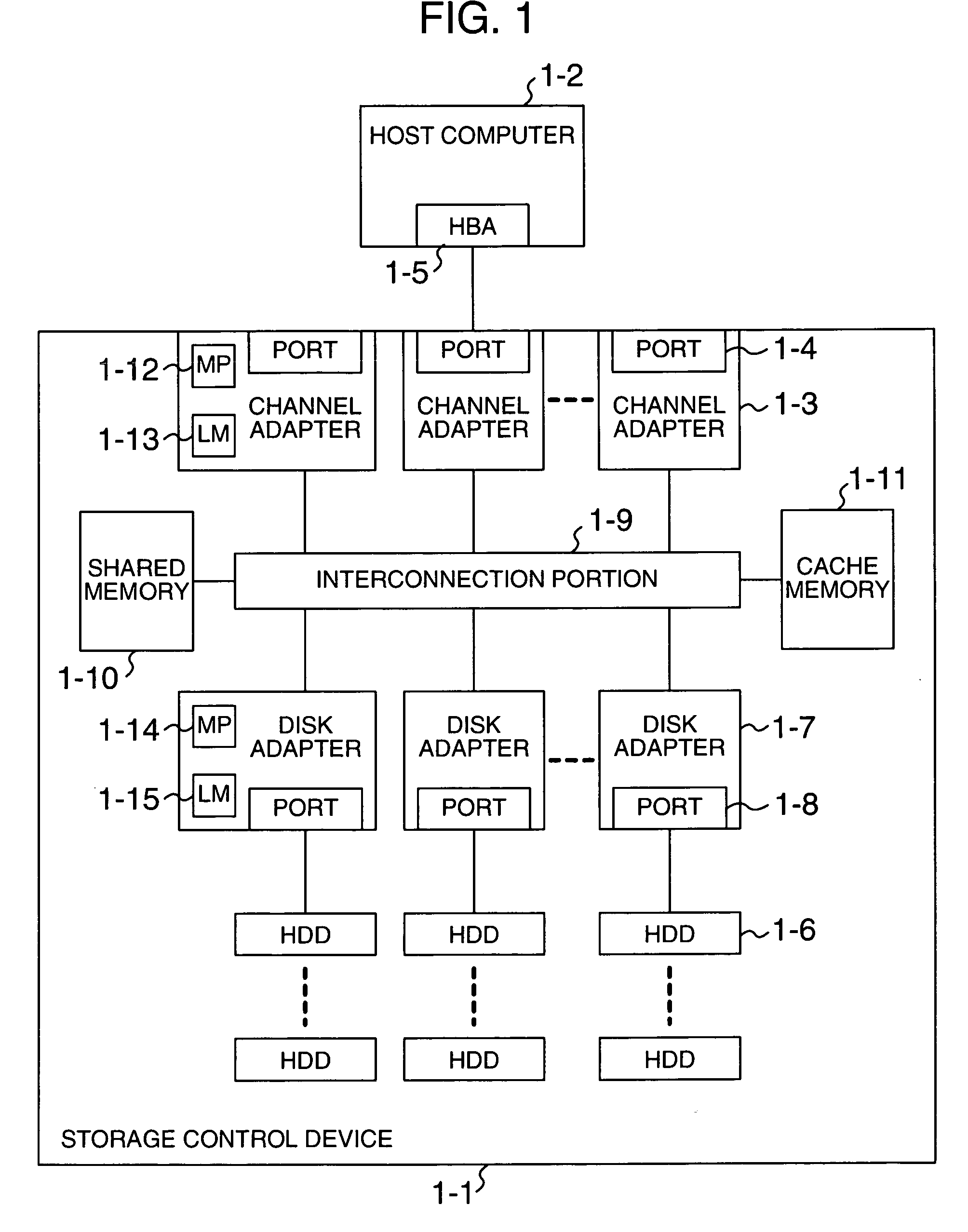
The present invention provides a storage control device which enables the time between failures to prolong as much as possible, though it uses HDD's whose mean time between failures is relatively short. The storage control device controls spindle motors in a manner that a spindle motor is rotated regarding the HDD of data which can access from a host computer and a spindle motor is stopped regarding the HDD of data which are clearly judged that a host computer does not access the data. Whether the host computers can access the HDD or not is judged by the fact that whether the memory region (internal logical volume) provided by the HDD is in mapped to the host logical volume or not which is recognized by the host computer and is able to access thereby.

Description

CROSS-REFERENCE TO RELATED APPLICATION [0001] This application relates to and claims priority from Japanese Patent Application No. 2003-428624, filed on Dec. 25, 2003, the entire disclosure of which is incorporated herein by reference. BACKGROUND OF THE INVENTION [0002] 1. Field of the Invention [0003] The present invention relates to a technique for controlling writing and reading of data from a upper device in a storage control device equipped with a plurality of disk drives. [0004] 2. Description of the Related Art [0005] There are hitherto the transaction and database as principal applications of the storage control device such as a disk array system. In such applications severe requirements are thus imposed as regards high performance and high reliability. Therefore, the storage control device used for this application is equipped with a hard disk drive (HDD) with high performance and high reliability. As the HDD fully complying with the imposed requirements must be highly reli...

Claims


Application Information

Patent Timeline
Patent Type & Authority Applications(United States)
IPC IPC(8): G06F12/00G06F3/06
CPCG06F3/0625Y02B60/1246G06F3/0689G06F3/0634Y02D10/00
Inventor HIGAKI, SEIICHIHONMA, HISAO
Owner HITACHI LTD
Learn More