
Wireless provider monitoring of catv segment

a technology of wireless provider and catv, which is applied in the direction of transmission, network data management, television systems, etc., can solve the problems of station occupying an important amount of real estate, microcells are usually limited in terms of their total available capacity, and the conventional implementation of mobile radio networks has had some important limitations

Inactive Publication Date: 2005-06-30
ZUSN MORDECHAI +3
View PDF8 Cites 100 Cited by
  • Summary
  • Abstract
  • Description
  • Claims
  • Application Information

AI Technical Summary

Benefits of technology

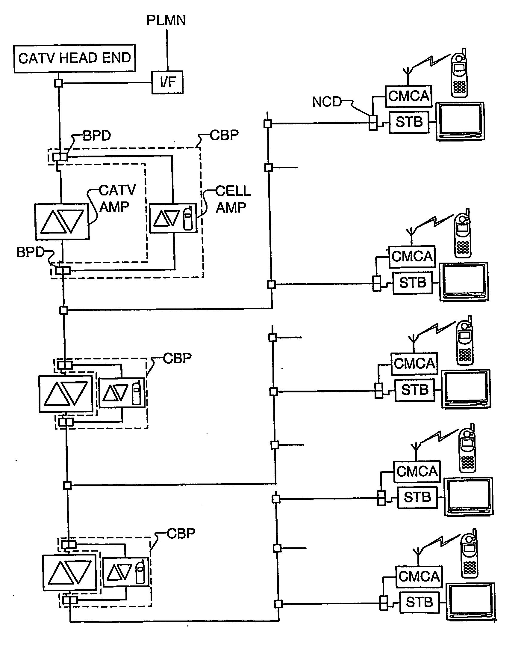
[0026] One objective, among others, is to overcome or mitigate the above identified disadvantages of mobile radio networks by making it possible for a wireless provider to monitor the CATV segment of a system and which cellular traffic is carried over a CATV network.
[0027] Another objective is to provide for a smaller cell size so as to make it possible for improved mobile terminal location operations, even to the level of locating an apartment or other premises in which the customer is in when communicating a call.
[0028] Another objective is to provide improved and sophisticated differential billing arrangements such as an advantageous price for a customer calling from his own premises, a different price for a customer calling from another customer's premises, and still another price for a non-customer calling from a customer's premises.
[0030] These monitor enabled devices make it possible for the wireless provider to query them, and to obtain certain status information. These monitor enabled devices also make it possible for the wireless provider to have an improved and simple mobile terminal location ability which, in turn, gives rise to the possibility of sophisticated differential billing arrangements.

Problems solved by technology

Microcells are usually limited in terms of their total available capacity.
The conventional implementation of mobile radio networks has had some important limitations.
The base stations require an important amount of real estate, and are very unsightly.
Another limitation is that, since cellular towers are expensive, and require real estate and costly equipment, it is economically feasible to include in a network only a limited number of them.
As the cell radius becomes larger, the average effective data rate per user in most packet based protocols decreases accordingly and the high-speed data service might deteriorate.
Yet another limitation to cellular radio networks as conventionally implemented is that the cellular antennas are typically located outside of buildings, even though it would be highly beneficial to provide cellular service inside buildings.
Because the base station antennas are usually located outside of buildings, it is difficult for mobile radio terminals to transmit signals strong enough to propagate effectively from inside of the building to outside of the building.
Therefore, the use of mobile terminals inside buildings results in reduced data rate and consumes substantial amount of the limited battery time.
Yet another limitation of UMTS, GSM900, GSM1800, PCS1900, TDMA800, CDMA800 or PDC radio networks as conventionally implemented is the inherent limited capacity of each and every BTS to provide voice and data service.
This capacity shortage is due to the way the spectrum resources are allocated to each BTS.
Unfortunately, the wireless provider has no way to know whether the CATV network is functioning properly, and cannot perform in a troubleshooting of the system without help from the CATV network provider.
Traditional cellular systems also suffer from the problem that it is difficult to locate a mobile terminal without complex triangulation calculations.
Furthermore, traditional cellular systems lacks the wherewithal to provide for sophisticated differential billing arrangements.
Both of these deficiencies arise from the fact that the size of cells is so large, even in the case of microcells.

Method used


Image

  • Wireless provider monitoring of catv segment
  • Wireless provider monitoring of catv segment
  • Wireless provider monitoring of catv segment

Examples


Embodiment Construction

[0059]FIG. 3 shows a CATV segment in a hybrid wireless / CATV system in which the invention is implemented. In FIG. 3, the wireless uplink and downlink frequencies are not converted into the normal bandwidth of the CATV system. Instead, the uplink and downlink frequencies are converted into a part of the bandwidth above the CATV programming. That is to say, wireless communications are all carried above 860 MHz.

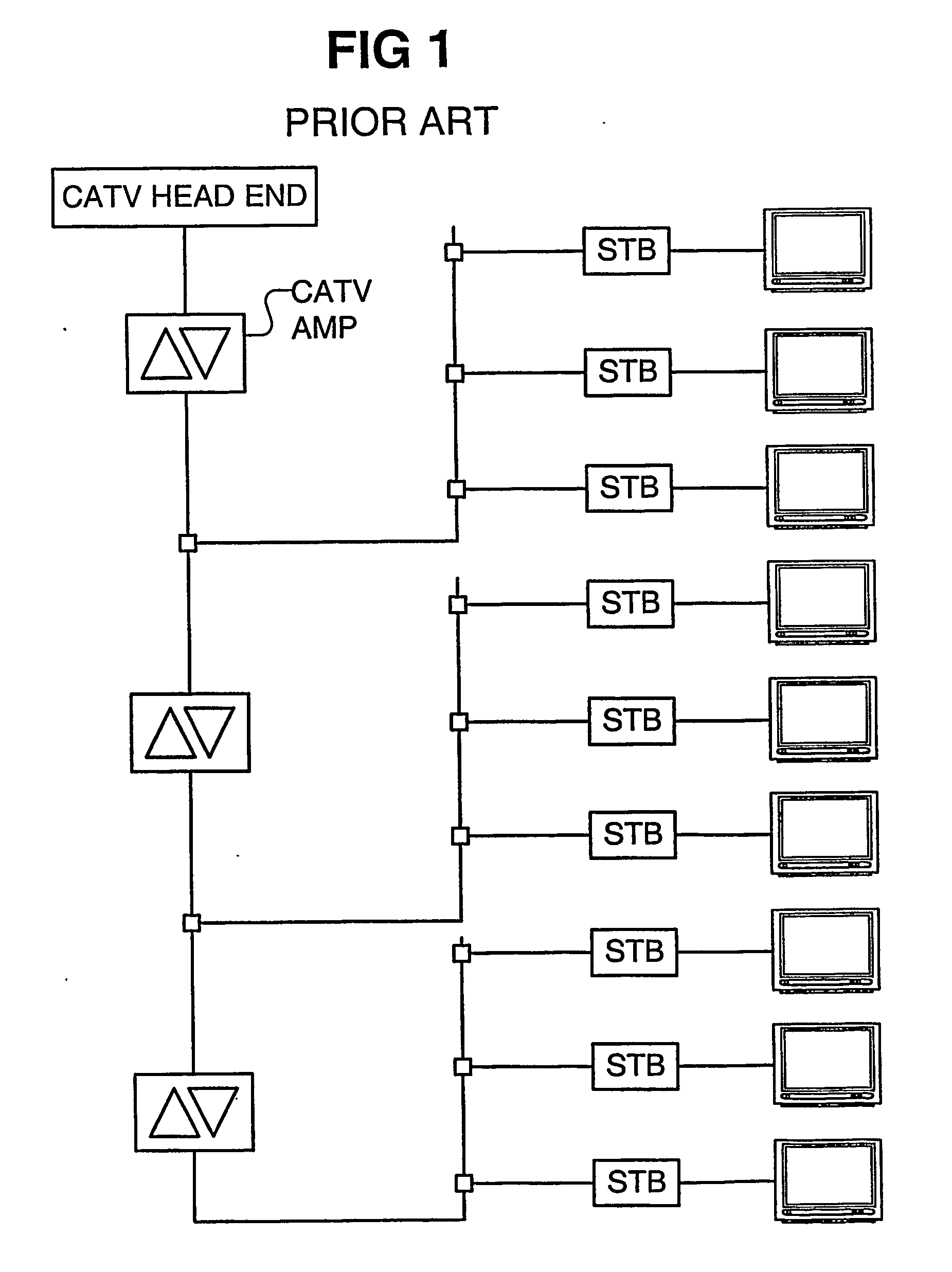
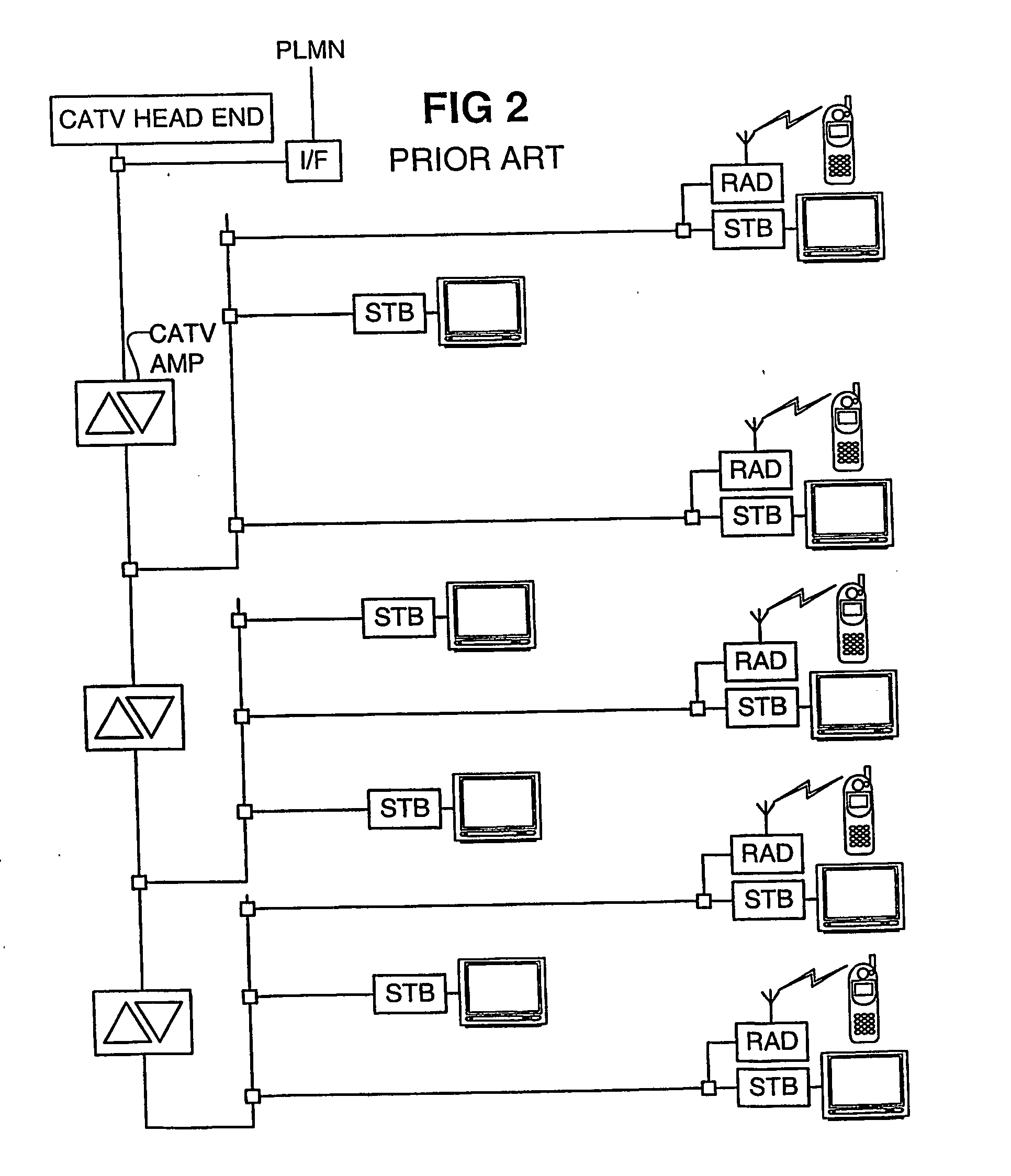
[0060] The CATV amplifier normally passes along only frequencies in the 5-45 MHz band for upstream communications, and filters out all other frequencies passing upstream. The CATV amplifier normally passes along only frequencies in the 50-750 / 860 MHz band for downstream communications, and filters out all other frequencies passing downstream. This poses a problem to carrying the cellular communications in a band above the normal CATV programming.

[0061] To overcome this problem, a cellular bypass (CBP) is installed at each active component (such as a CATV amplifier). The CBP in...


PUM


Abstract

A monitor enabled amplifier in the CATV segment of a wireless network includes a cellular interface communicating with a network control center to provide status information pertaining to the CATV network. A monitor enabled cable Mount cellular antenna with a twin mode cellular interface provide status and location correlation information to the network control center. The location correlation information supports an emergency response system and differential billing.

Description

CROSS-REFERENCE TO RELATED APPLICATIONS [0001] This application claims the benefit of U.S. Provisional Application No. 60 / 357,650, filed on Feb. 20, 2002, the disclosure of which is incorporated herein by reference, in its entirety, for all purposes.BACKGROUND [0002] 1. Field of the Invention [0003] This description relates to the monitoring of a system for providing cellular service over a CATV or similar network In particular, this description relates to providing a method and equipment for enabling a wireless provider to monitor cellular activity over a CATV segment. As used herein, the term “cellular” generally refers to any wireless communications, and includes, but is not limited to, the following systems: UMTS, GSM, PCS, CDMA, TDMA, and PDC type networks. [0004] 2. Description of Related Art [0005] The advantages of using a CATV system for carrying cellular traffic can be readily grasped by looking at the disadvantages of traditional cellular systems. [0006] The basic theory ...

Claims


Application Information

Patent Timeline
IPC IPC(8): H04L12/56H04N7/10H04N7/173H04W4/18H04W8/24H04W64/00H04W84/04
CPCH04M2215/2026H04M2215/32H04N7/10H04N7/102H04N7/17309H04W84/045H04W4/24H04W8/245H04W64/00H04W84/042H04W4/18
Inventor ZUSSMAN, MORDECHAIANGHEL, MICHAELZUSSMAN, HARELSHKLARSKY, DAN
Owner ZUSN MORDECHAI
Learn More