

Method for manufacturing substrate, release sheet, substrate manufacturing apparatus and method for manufacturing substrate using same
- Summary
- Abstract
- Description
- Claims
- Application Information
AI Technical Summary
Benefits of technology
Problems solved by technology
Method used
Image

Examples
exemplary embodiment 1
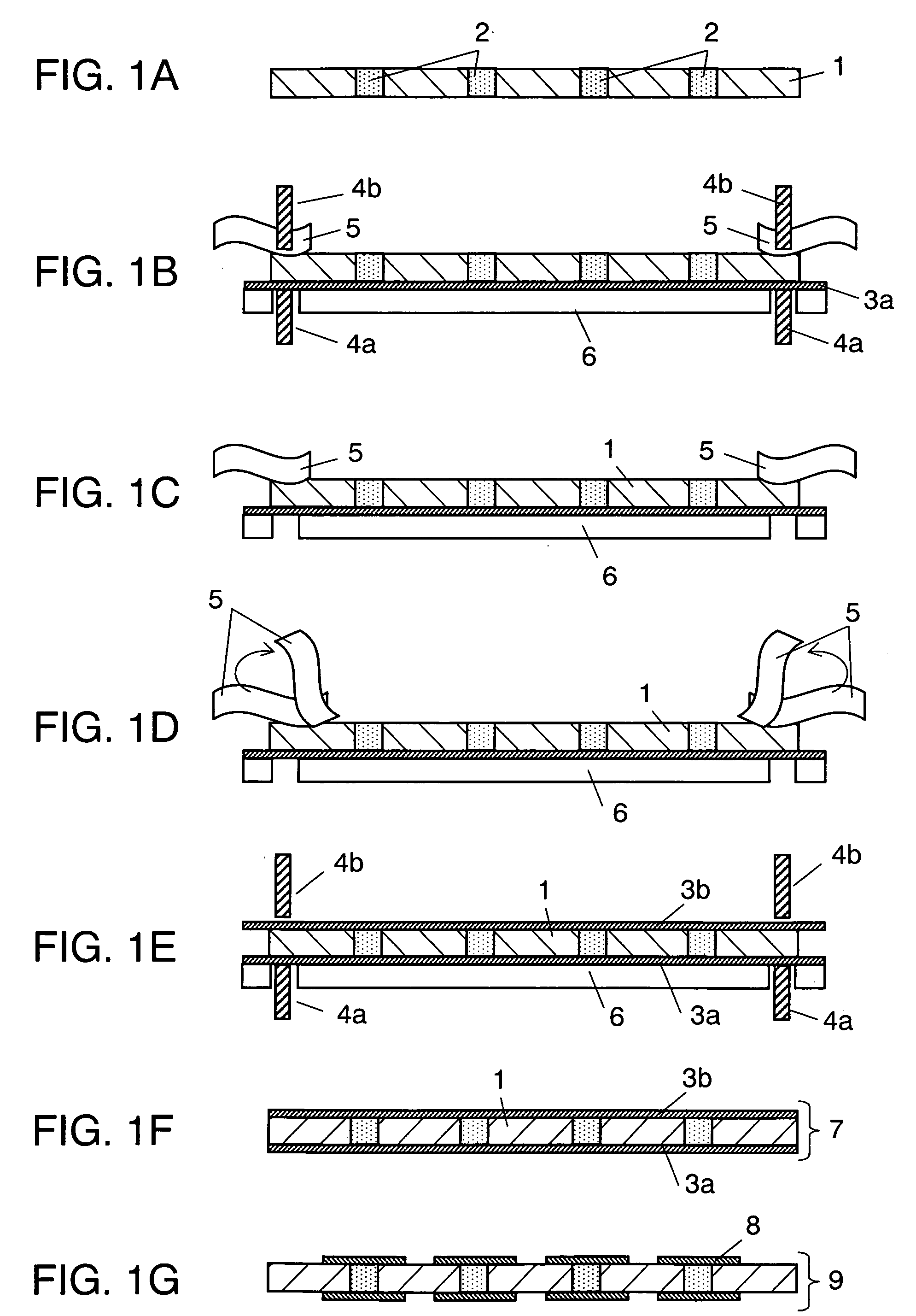
[0079]FIG. 1A-FIG. 1G show sectional views illustrating steps of manufacturing double-sided boards (two layers) which are to be inside core boards of multi-layer boards in accordance with the first exemplary embodiment of the present invention.
[0080]FIG. 1A shows aramid-epoxy sheet (hereinafter referred to as prepreg) 1 formed of composite in which aromatic polyamide non-woven fiber, of which dimensions are 400 mm square and 150 μm thick, is impregnated with thermosetting epoxy resin, and via 2 filled with conductive paste by printing. Via 2 is a through hole processed by laser beam.
[0081]FIG. 1B shows copper foil 3a situated on positioning stage 6, heater-punches 4a, 4b having a tip of approx. 10 mm across and working as a heating means, and mold-releasing sheet 5. The releasing properties of sheet 5 are increased by applying silicon to polypheneylene-sulfide of 75 μm thick. When sheet 5 is solidly pressed onto prepreg 1, the side undergone the release-process is brought into con...
exemplary embodiment 2
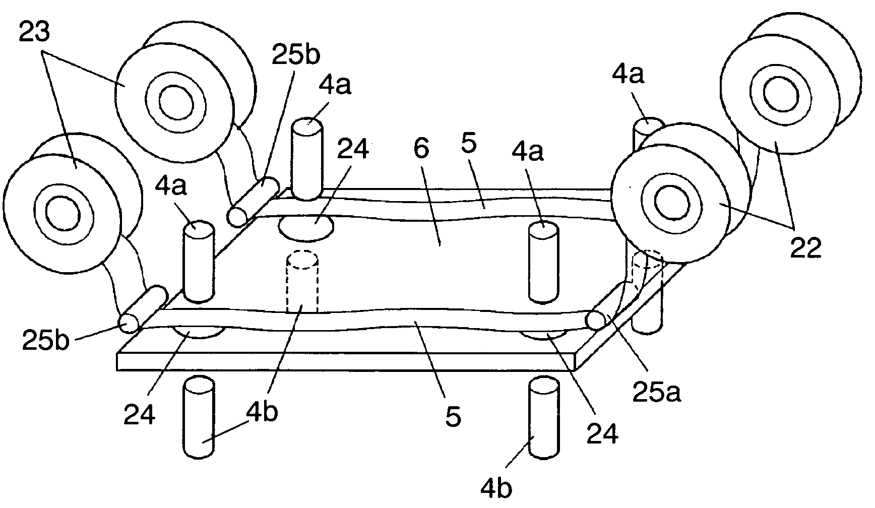
[0108]FIG. 3 shows a perspective view of a manufacturing apparatus for manufacturing the boards of the present invention. FIG. 3 shows heater-punches 4a, 4b to be used as heating means, and positioning stage 6 having pressuring holes 24 at given places for pressing an underside of a board. Supply reels 22 are disposed at given places on one side of stage 6 for supplying mold-releasing sheet 5, and tape-like mold-releasing sheet 5 is wound on a plastic core, and this core is mounted to respective reels 22.
[0109] Sheet 5 supplied from reel 22 is guided by guide-roll 25a and fed onto stage 6, and travels through heater-punches 4a and 4b, which are disposed at given places on stage 6, such that sheet 5 divides the heater punches into upper section 4a and lower section 4b. Then sheet is guided by guide roll 25b and taken up by take-up reel 23.
[0110] Placement of sheet 5 as shown in FIG. 3, namely, placement of four pairs of heater-punches 4a and 4b, allows bonding at four places at one...
exemplary embodiment 3
[0112] An operation of the manufacturing apparatus for the boards of the present invention is demonstrated with reference to FIGS. 4A-4E. In this demonstration, descriptions are particularly focused to the following two steps: solidly pressing prepreg 1 after prepreg 1 is laminated on copper foil 3a, and peeling-off mold-releasing sheet 5.
[0113]FIG. 4A shows prepreg 1 positioned and situated on copper 3a placed on positioning stage 6. Sheet 5 is disposed over prepreg 1, and supplied from supply reel 2. Sheet 5 is then guided by guide roll 25b and taken up by take-up reel 23. Both of supply reel 22 and take-up reel 23 have a tension adjusting function.
[0114]FIG. 4B shows the steps of heating and pressing by heater-punches 4a, 4b. Pressing heater-punches 4a, 4b prompts the following elements to lower almost at the same time: supply reel 22, guide rolls 25a, 25b, mold-releasing sheet 5, a supplying and discharging means (it is called a mold-releasing unit) of take-up reel 23. Tension...
PUM
| Property | Measurement | Unit |
|---|---|---|
| Temperature | aaaaa | aaaaa |
| Diameter | aaaaa | aaaaa |
| Thermal resistance | aaaaa | aaaaa |
Abstract
Description
Claims
Application Information