
Apparatus for heating optical fiber preform and method for manufacturing optical fiber preform

a technology of optical fiber and heating apparatus, which is applied in the direction of glass furnace apparatus, glass making apparatus, manufacturing tools, etc., can solve the problems of affecting the quality of manufactured optical fiber glass preforms. , to achieve the effect of increasing the temperature of each heating sour

Inactive Publication Date: 2005-07-07
SAMSUNG ELECTRONICS CO LTD
View PDF0 Cites 4 Cited by
  • Summary
  • Abstract
  • Description
  • Claims
  • Application Information

AI Technical Summary

Benefits of technology

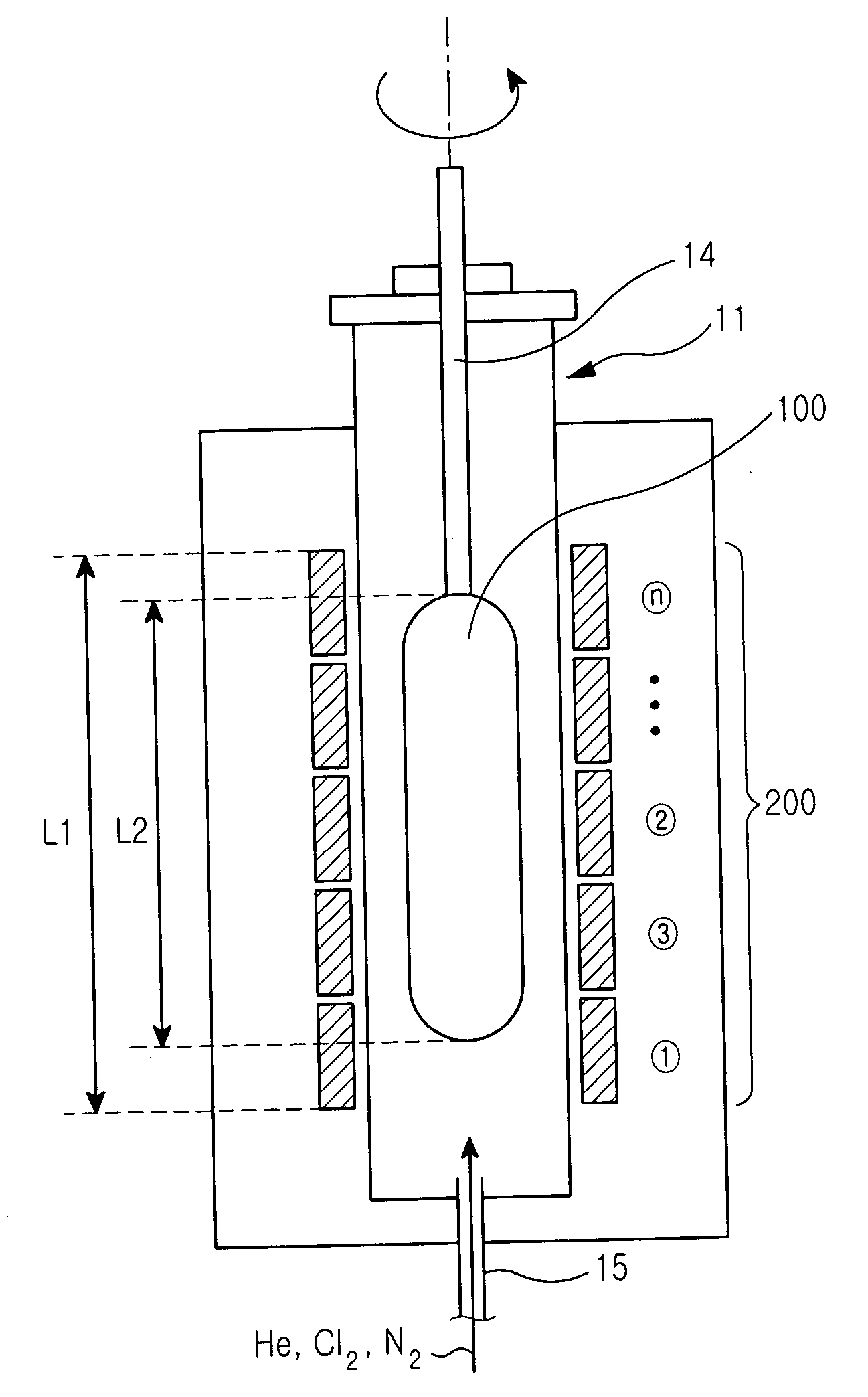
[0013] Accordingly, the present invention has been made to solve above-mentioned problems occurring in the prior art and provides additional advantages, by providing an apparatus for heating an optical fiber preform and a method for manufacturing the same. The invention improves the heat treatment process for products by uniformly performing a dehydration process with respect to the optical fiber preform using a plurality of heating sources stacked in the heating apparatus.
[0014] Another aspect of the present invention is to provide an apparatus for heating an optical fiber preform and a method for manufacturing the same, in which the optical fiber preform is vertically aligned and heated by means of a plurality of stacked heating sources, so that the length of a muffler provided in the heating apparatus can be shortened, thereby uniformly maintaining pressure in the muffler and reducing the amount of gas supplied into the muffler.
[0015] Still another aspect of the present invention is to provide an apparatus for heating an optical fiber preform and a method for manufacturing the same, in which the optical fiber preform is vertically aligned and heated by means of a plurality of stacked heating sources, so that the length of a support rod connected to the optical fiber preform can be shortened, thereby reducing the height of equipment.
[0017] In another embodiment, there is provided a method for manufacturing a porous optical fiber preform which includes the steps of: forming soot consisting of glass particles and forming a soot preform by performing a primary heat-treatment process with respect to the soot preform; inputting the soot preform into a muffler provided at both sides thereof with at least two heating sources, which are aligned lengthwise along the soot preform; rotating the soot preform within the heating sources, injecting inert gas into the muffler, and performing a primary dehydration and dry process by increasing the temperature of each heating source; and, ejecting an optical fiber preform from the muffler after performing a secondary heat treatment process with respect to the soot preform by sequentially increasing the temperature of the heating sources according to a predetermined order.

Problems solved by technology

If more than 1 ppb of the transition metal element is mixed with the optical fiber glass preform, a transmission loss wavelength characteristic of the manufactured optical fiber glass preform is significantly deteriorated throughout all of the wavelengths.
Further, if more than 0.1 ppm of moisture is mixed with the optical fiber glass preform, various characteristics of the manufactured optical fiber glass preform are damaged over a wide range of wavelengths.
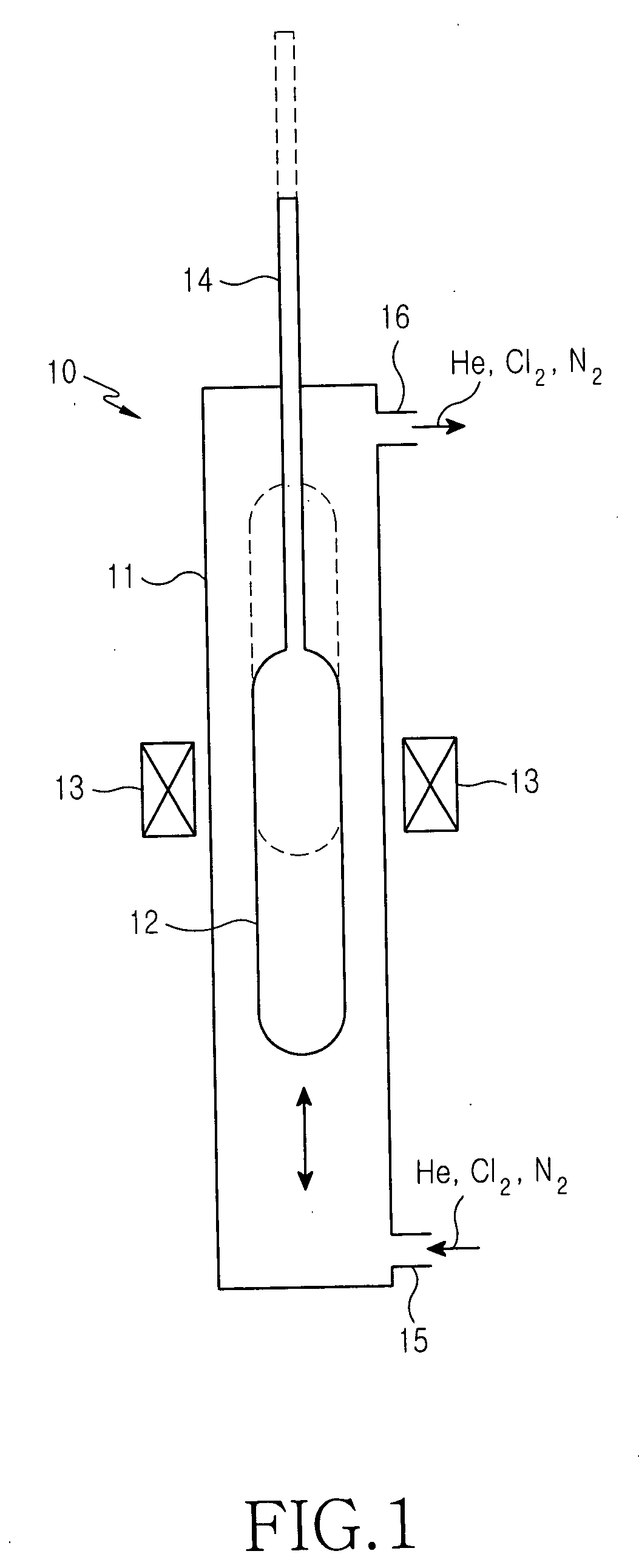
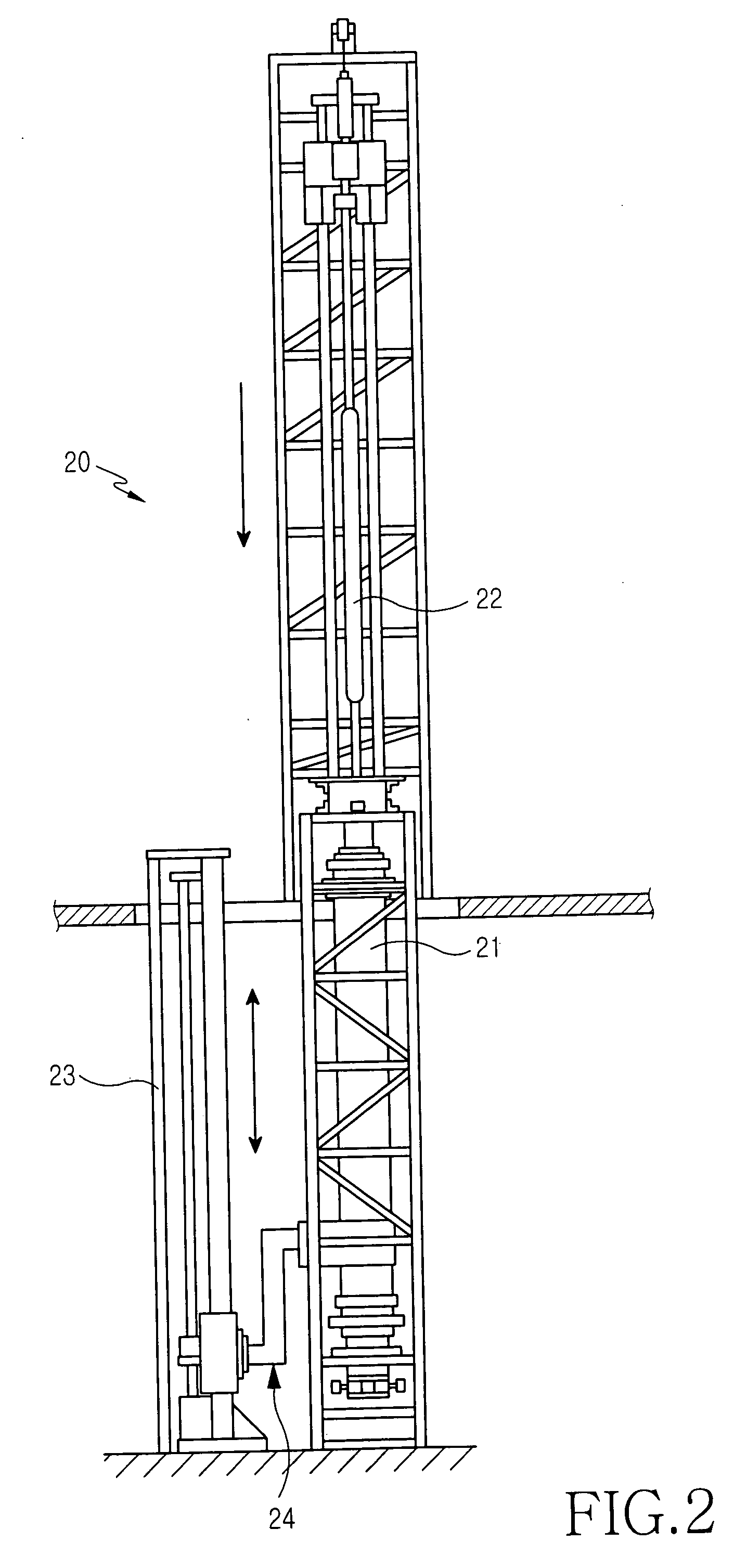
However, the height of equipment for performing the zone-sintering heat treatment process is higher than the full-sintering heat treatment process, and the manufacturing cost for such equipment is very expensive.
If the height of equipment becomes high, manufacturing processes for an article may be complicated and the height of a factory also must become high, so maintenance cost is increased.
In addition, because the volume of the muffler is enlarged, the amount of gas consumption may be increased.
As such, the number of parts of the heating apparatus may be increased, thus resulting in expensive manufacturing cost.
Moreover, in order to prevent the muffler from being cooled and a carbon susceptor from being oxidized, the chamber has a complex structure including many layers forming a gas injection inlet, an auxiliary heater, and an insulation member, so excessive power is consumed.

Method used


Image

  • Apparatus for heating optical fiber preform and method for manufacturing optical fiber preform
  • Apparatus for heating optical fiber preform and method for manufacturing optical fiber preform
  • Apparatus for heating optical fiber preform and method for manufacturing optical fiber preform

Examples


Embodiment Construction

[0023] Referring to FIG. 3, a heating apparatus for manufacturing an optical fiber preform includes a muffler 11, and a gas injection inlet 15 formed at a lower portion of the muffler 11 to provide gas into the muffler 11. The optical fiber preform 100 is vertically disposed in the muffler 11. At least two heating sources 200 are vertically provided at both sides of the muffler 11 lengthwise along the optical fiber preform 100 in such a manner that the optical fiber preform 100 accommodated in the muffler 11 can be heat-treated according to a rotation of the optical fiber preform 100. In addition, the optical fiber preform 100 is a porous optical fiber preform, and is vertically and rotatably installed. The heating sources 200 are fixedly stacked in a vertical direction, thereby forming a furnace. The heating sources 200 forming the furnace can be rotated.

[0024] The temperature of the heating sources 200 gradually rises from a lower portion of the optical fiber preform 100 towards ...


PUM

PropertyMeasurementUnit
Temperatureaaaaaaaaaa
Lengthaaaaaaaaaa
Shapeaaaaaaaaaa

Abstract

An apparatus for heating an optical fiber preform and a method for manufacturing the optical fiber preform are disclosed, in which the optical fiber preform aligned in a vertical direction is heated by stacked heating sources. The apparatus for heating the optical fiber preform includes a muffler accommodating the optical fiber preform therein, and at least two heating sources aligned lengthwise along the optical fiber preform.

Description

CLAIM OF PRIORITY [0001] This application claims priority to an application entitled “Apparatus for Heating Optical Fiber Preform and Method for Manufacturing Optical Fiber Preform,” filed in the Korean Intellectual Property Office on Jan. 6, 2004 and assigned Ser. No. 2004-773, the contents of which are hereby incorporated by reference. BACKGROUND OF THE INVENTION [0002] 1. Field of the invention [0003] The present invention relates to an apparatus for heating an optical fiber preform and a method for manufacturing the same, and more particularly to an apparatus for heating an optical fiber preform, which is aligned in a vertical direction by stacked heating sources. [0004] 2. Description of the Related Art [0005] Generally, a VAD method (vapor-phase axial deposition method) is known in the art as a method for manufacturing masses of glass preforms used for fabricating optical fibers. According to the VAD method, a cylindrical optical fiber preform (soot preform) is formed by depos...

Claims


Application Information

Patent Timeline
IPC IPC(8): C03B37/10C03B37/014
CPCC03B37/0146C03B37/10
Inventor YOON, YOUNG-SIKDO, MUN-HYUN
Owner SAMSUNG ELECTRONICS CO LTD
Learn More