[0007] The present invention provides a new
machine and process to make a cross-lapped flat-
tube structure or batting of crimped continuous filaments with optimum balance of tensile strength in all directions, especially in machine (MD) and cross-machine (CD) directions, with good stretch
recovery properties, dimensional stability, and high loft, and overcomes the important deficiencies mentioned above in the prior art.
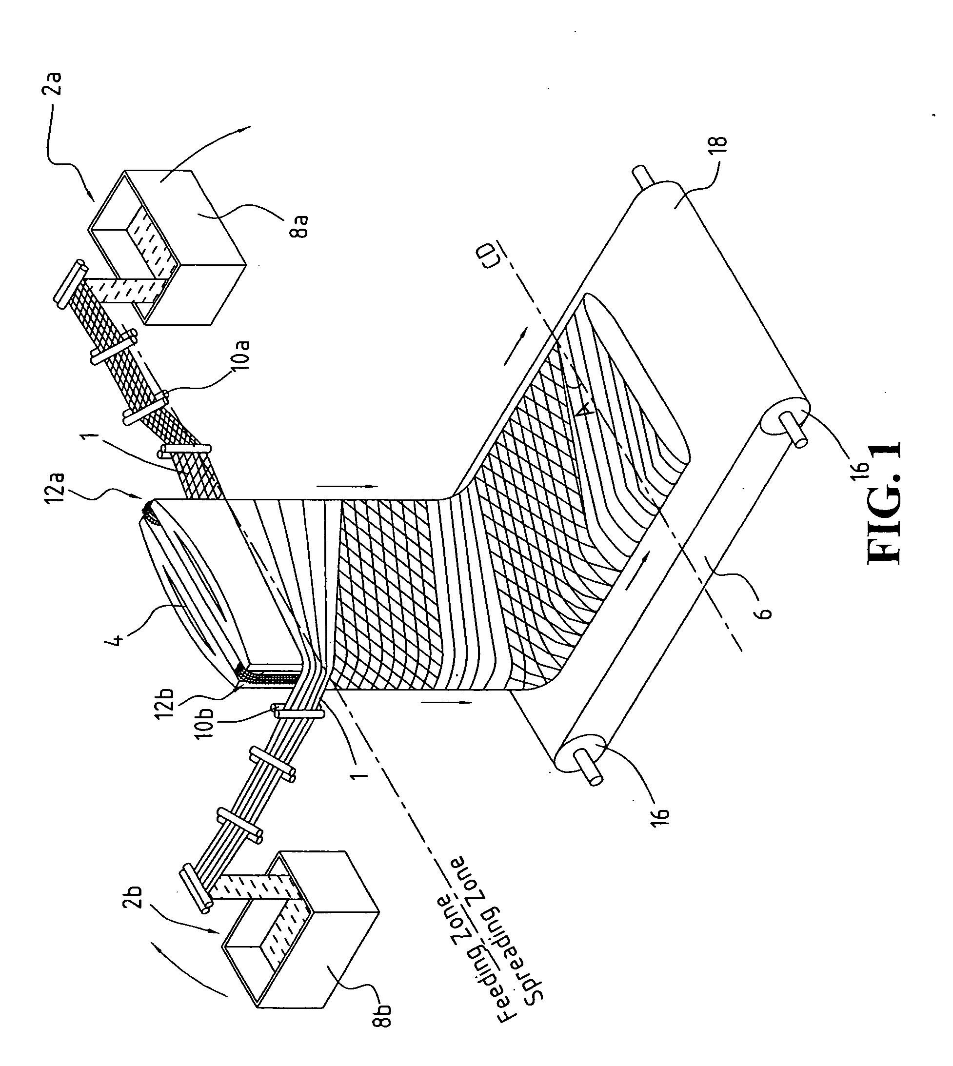
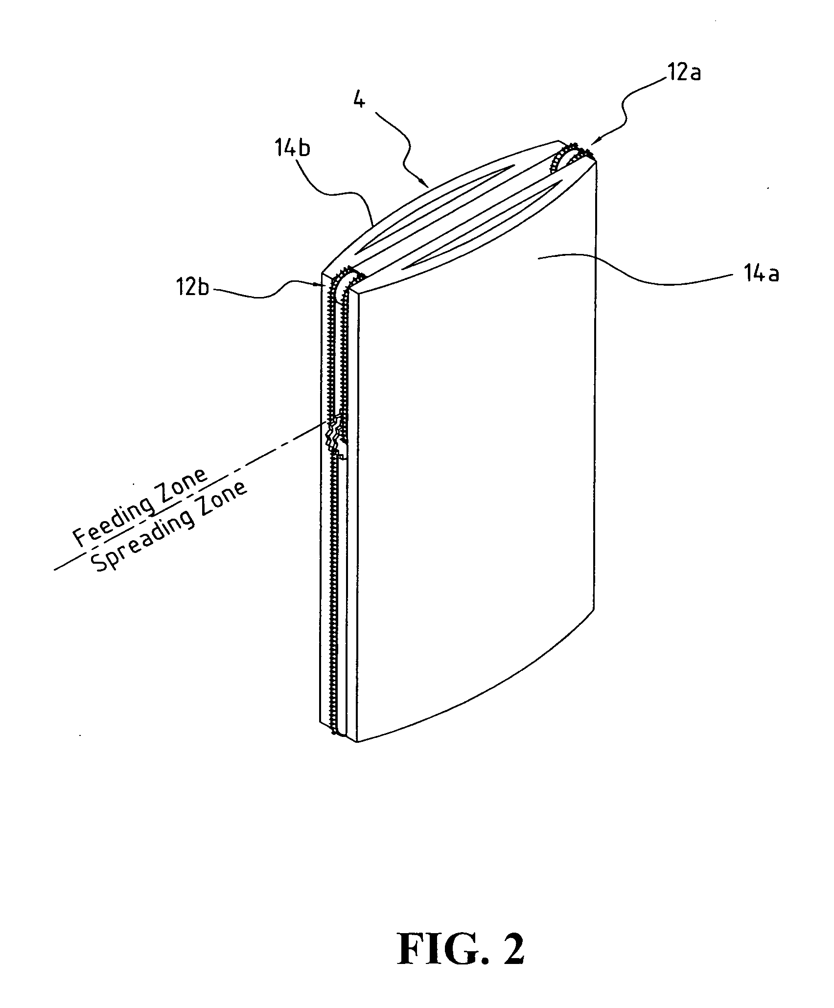
[0008] This invention uses crimped continuous filaments tow band wrapping at constant tension and speed around a batt-forming device which spreads, extends, and cross-laps this tow continuously to form a uniform batting having balanced tensile strength and to provide
structural stability and stretch
recovery properties. Uncrimped continuous filaments having extendible properties, such as elastic fibers or latent crimped fibers, etc., which can be spread, extended, and cross-lapped can also be used with this invention. By adjusting the traveling speed of the tow band wrapping around the batt-forming device and the spread belt surface speed in the spreading zone as described below as a spread ratio in the batt-forming device, the
fiber orientation can achieve between a 10- and 70-degree angle, preferably a 30- to 60-degree angle, vs. the CD direction, and achieve a
fiber orientation between cross-lapped
layers of close to a 20- to 140-degree angle, preferably a 60- to 120-degree angle. As an example, when the traveling speed of the tow band wrapping around the batt-forming device and the spread ratio are optimized, the
fiber orientation can be maintained at about a 45-degree angle vs. the CD direction, and the
fiber orientation between cross-lapped layers at close to a 90-degree angle. This combination of
fiber orientation in a spread flat-
tube structure provides the best balance in MD and CD strength with a ratio of 1:1 so that there are essentially no weak spots in the cross-lapped flat-tube structure regardless of which direction the structure is pulled. The resulting cross-lapped flat-tube structure also exhibits excellent stretch
recovery properties, dimensional stability, and high loft. Since the cross-lapped structure is formed from continuous filaments into an endless flat tube with good cohesion between individual fibers and between spread tow layers, one can use it directly without additional
bonding process for insulated apparel, sleeping bags,
bedding articles, and furniture applications, thus eliminating the deficiencies of the conventional cross-lapped batting made by the prior art mentioned above.
[0009] The
advantage of wrapping the batt-forming device under constant tension and speed throughout the spreading, extending, and cross-lapping process eliminates the deficiency of the prior art of forming a thinner web on the lateral edges and the weight uniformity problem, especially in the midline of the final batting. By adjusting the traveling speed of the feeding device and the spread ratio of the forming device, a complete balance of the tensile strength and stretchability in MD and CD directions can be achieved, hence eliminating the deficiencies of the prior art, which has poor tensile strength and dimensional stability in the MD, or longitudinal, direction. Also the need for
resin bonding, needle
punching, or
thermal bonding to improve cohesion between layers in the conventional cross-lapped structure can be eliminated, resulting in a stretchable, softer, and thicker structure to improve the aesthetics and warmth of the sleeping bags, insulated apparel, etc. These aspects of the present invention may be used separately or in combination to solve deficiencies of the conventional cross-lapped structure.
[0010] Because of the unique
fiber orientation achieved by this invention and the precision control of the batting width, the cross-lapped flat-tube structure maintains the strength
advantage of the spun bonded fabric but with improved stretchability, loft, and softness vs. spun bonded fabric. No resin, or
thermal bonding, or mechanical entanglement such as needle
punching is required for the cross-lapped flat-tube structure of this invention. If desired, one can also use the above conventional bonding processes to even further increase the batting strength but with increased stiffness.
[0011] Because the cross-lapped structure by this invention is formed under pre-determined constant tension and precise mechanically controlled spreading, extending, and cross-lapping, the stress applied on each filament is similar. Once the cross-lapped structure is released from the spread belt and is delivered to the conveyor, it maintains its dimensional stability and uniformity in this relaxed state. This cross-lapped flat tube structure can be used for insulated apparel, sleeping bags,
bedding, and furniture applications without further bonding steps such as
resin bonding, needle
punching, and
thermal bonding with low-melting binder fiber, which normally reduce softness and / or loft. Due to the unique stretchability property of the cross-lapped flat tube structure of this invention, it can easily regenerate its loft and resiliency from compression during shipping and storage by slightly stretching or fluffing the final products. Particularly useful when a stretchable cover fabric or shell fabric is used is the ability of the flat-tube structure of this invention to conform to the stretching of the fabric without deterioration. The conventional resin bonded, needle-punched, and thermally bonded batting or cross-lapped structure cannot provide this regeneration property because individual fibers and cross-lapped layers are bonded and locked with each other and are not free to separate from the compressed bonded structure.
[0012] The differences between the cross-lapped flat-tube structure of this invention and spun bonded fabric are significant. The present invention allows fiber orientation at a 45-degree angle vs. the CD direction and a 90-degree angle between cross-lapped layers of spread tow for balanced strength. The resulting structure can be used directly without bonding vs. spun bonded batting, which must be bonded to stabilize the structure. Hence the cross-lapped flat-tube structure of this invention is softer and provides higher loft. In addition, the continuous filaments used in this invention can be crimped as an option vs. no
crimp for spun bonded filaments directly extruded from spinnerets, therefore exhibiting its stretch recovery properties. Spun bonded battings are limited to low fiber orientation angles, no
crimp in each filament, and a rigidly bonded structure leading to rigid and low-loft
nonwoven fabric or batting.

