Transseptal needle

a transseptal needle and needle tip technology, applied in the direction of guide needles, dilators, surgery, etc., can solve the problems of bloodstream posing a hazard, reduce the potential for skiving or particle production, and minimize the production of particles.

Inactive Publication Date: 2005-07-07
BOSTON SCI SCIMED INC
View PDF11 Cites 113 Cited by
  • Summary
  • Abstract
  • Description
  • Claims
  • Application Information

AI Technical Summary

Benefits of technology

[0011] In accordance with one or more configurations of the needle combinations described herein, skiving or production of particles can be reduced, and methods can be used that reduce the production of particles in needle assemblies. For example, the potential for skiving can be reduced by incorporating needle assemblies that protect surfaces adjacent to the needle tip to minimize the production of particles through contact between the needle tip and adjacent surfaces. Such needle assemblies may be particularly useful when used with transseptal dilator tubes having a pre-formed curvature. Such assemblies can be used in other applications as well.
[0013] In another example of a needle assembly, a hollow element, for example a dilator, includes a sleeve movable within the hollow element. The sleeve is formed from a first material having a first hardness. A needle within the sleeve includes a tip formed from a material having a second hardness no greater than the first hardness. In one configuration, the sleeve protects the hollow element from the needle tip, thereby reducing possible production of particles that might occur if the needle tip were to contact an inside surface of the hollow element. In examples described herein, the needle may be a transseptal needle, such as one formed from hypotube. The needle may have a conventional pointed tip and hollow interior, for example for accepting a stylet and / or for measuring blood pressure. Alternatively, the needle may be closed ended, and may have side openings for passing fluid from the needle.
[0014] In an additional example of a needle assembly, the assembly includes a hollow element, for example a dilator, and a sleeve movable within the hollow element. A needle is positioned within the sleeve and is formed from a material no harder than the sleeve. The sleeve includes a distal end portion that has a converging surface portion, and may include a tapered distal end, a rounded end portion, or other similar distal end configuration. The sleeve may be segmented, for example with one segment harder than the other segment, with the harder segment being adjacent to the needle tip. The presence of the harder segment may reduce the likelihood of particles being created during movement of the needle.
[0017] Needle assemblies can also be used in ways to reduce the possibility of generating particles. In one example of a needle and dilator combination, a transport tube having a portion formed from a first material may be introduced into the dilator, and a needle formed from a material no harder than the first material may be moved within the transport tube. Movement of the needle within the transport tube rather than along the surface of the dilator helps to reduce the possibility of skiving or otherwise generating particles. In one series of steps, the needle may be introduced into the transport tube prior to the transport tube being introduced into the dilator. Additionally, the needle tip may be kept within the transport tube until such time as the transport tube is positioned at the desired location relative to the dilator. In some configurations, all contact between the needle and the dilator may be precluded.

Problems solved by technology

Any of these particles which may enter the bloodstream may pose a hazard as an embolus.

Method used


Image

  • Transseptal needle
  • Transseptal needle
  • Transseptal needle

Examples


Embodiment Construction

[0045] The following is a detailed description of the best presently known modes of carrying out the inventions. This description is not to be taken in a limiting sense, but is made merely for the purpose of illustrating examples of apparatus and methods incorporating one or more aspects of the present inventions.

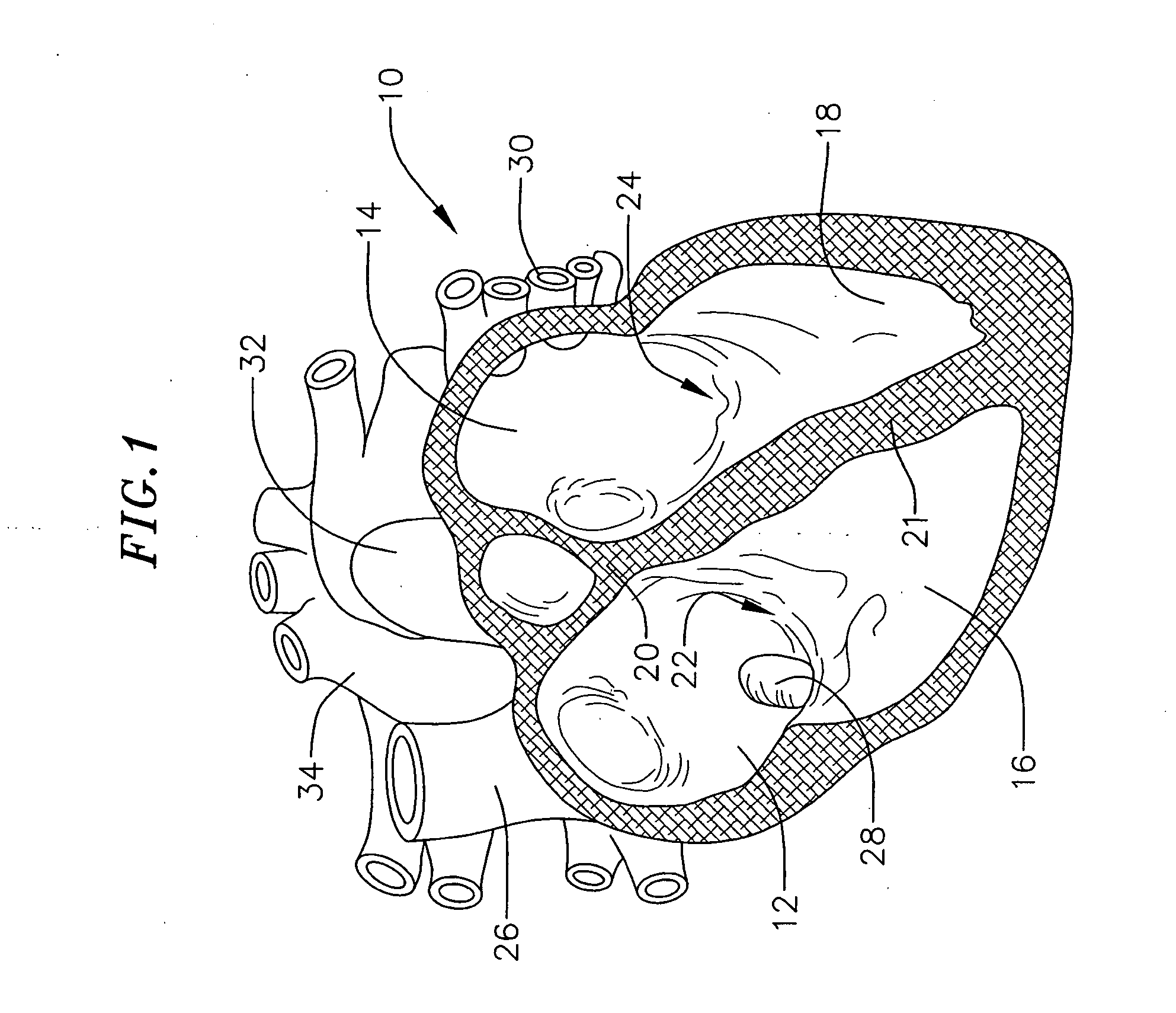
[0046] One or more aspects of the apparatus and methods described herein may be used within body lumens, chambers or cavities for diagnostic or therapeutic purposes such as, for example, in those instances where access to internal body regions is had through the vascular system, alimentary canal or other vessels without complex invasive surgical procedures. The apparatus and methods described herein may, for example, be used during the diagnosis or treatment of heart conditions. They may also have application in the diagnosis or treatment of conditions in other regions or organs of the body such as the prostate, liver, brain, gall bladder, uterus and other solid organs. Th...


PUM


Abstract

A transseptal needle and other structures and methods may include an outer conduit, for example one that may be subject to skiving, and a needle or other sharp structure within the outer conduit. A material no softer than the needle is positioned between the needle and the outer conduit so that the needle does not skive the inside surface of the outer conduit when the needle and outer conduit move relative to each other.

Description

BACKGROUND OF THE INVENTIONS [0001] 1. Field of Inventions [0002] The present inventions are directed to methods and apparatus relating to the use of needles, including transseptal needles, and other structures and procedures for traversing tissue areas within areas of blood flow. [0003] 2. Related Art [0004] Various procedures exist for accessing a blood flow area across a tissue wall for monitoring, diagnosis or treatment. In one example, though not the only situation where an instrument crosses a tissue wall into a blood flow area, a physician may want to access the left side of the heart from the right side by crossing a septum dividing the right atrium from the left atrium. The physician may be trying to access the tissue walls of the left atrium, heart valves on the left side of the heart, or other structures or regions on the left side of the heart. The physician may, for example, intend to form therapeutic lesions in the left atrium to treat cardiac conditions such as atrial...

Claims


Application Information

Patent Timeline
Patent Type & Authority Applications(United States)
IPC IPC(8): A61M25/00
CPCA61M25/0068A61M25/008A61M2025/0681A61M2025/0004A61M2025/0089A61M25/0084
Inventor REGNELL, SANDRA J.FORREST, MARKSUBRAMANIAM, RAJ
Owner BOSTON SCI SCIMED INC
Why Eureka
Try Eureka