Optical processing

a technology of optical processing and optical fiber, applied in the field of optical processing, can solve the problems of limited acceptance and often demanding decompression, and achieve the effect of reducing interactions

Inactive Publication Date: 2005-07-07
LENSLET
View PDF71 Cites 29 Cited by
  • Summary
  • Abstract
  • Description
  • Claims
  • Application Information

AI Technical Summary

Benefits of technology

[0020] In some embodiments of the invention, two or more of the optical elements are integrated into a single element, for example, the SLM and the lens, the SLM and the detector or the lens and the detector. In one example, the detector is partially reflective (and/or a polarizing beam splitter) and is curved, to act as a lens. A second mirror (optionally polarization affecting) returns the light processed by the lens effect of the detector, to the detector, for detection. In some embodiments, two light beams are thus provided, a processed beam and an unprocessed beam that can be used as a reference beam for various uses.
[0021] An aspect of some embodiments of the invention relates to reducing interactions between light from adjacent pixels

Problems solved by technology

Compression and in some cases decompression are often very demanding and typically require dedicated hardware.
However,

Method used


Image

  • Optical processing
  • Optical processing
  • Optical processing

Examples


Embodiment Construction

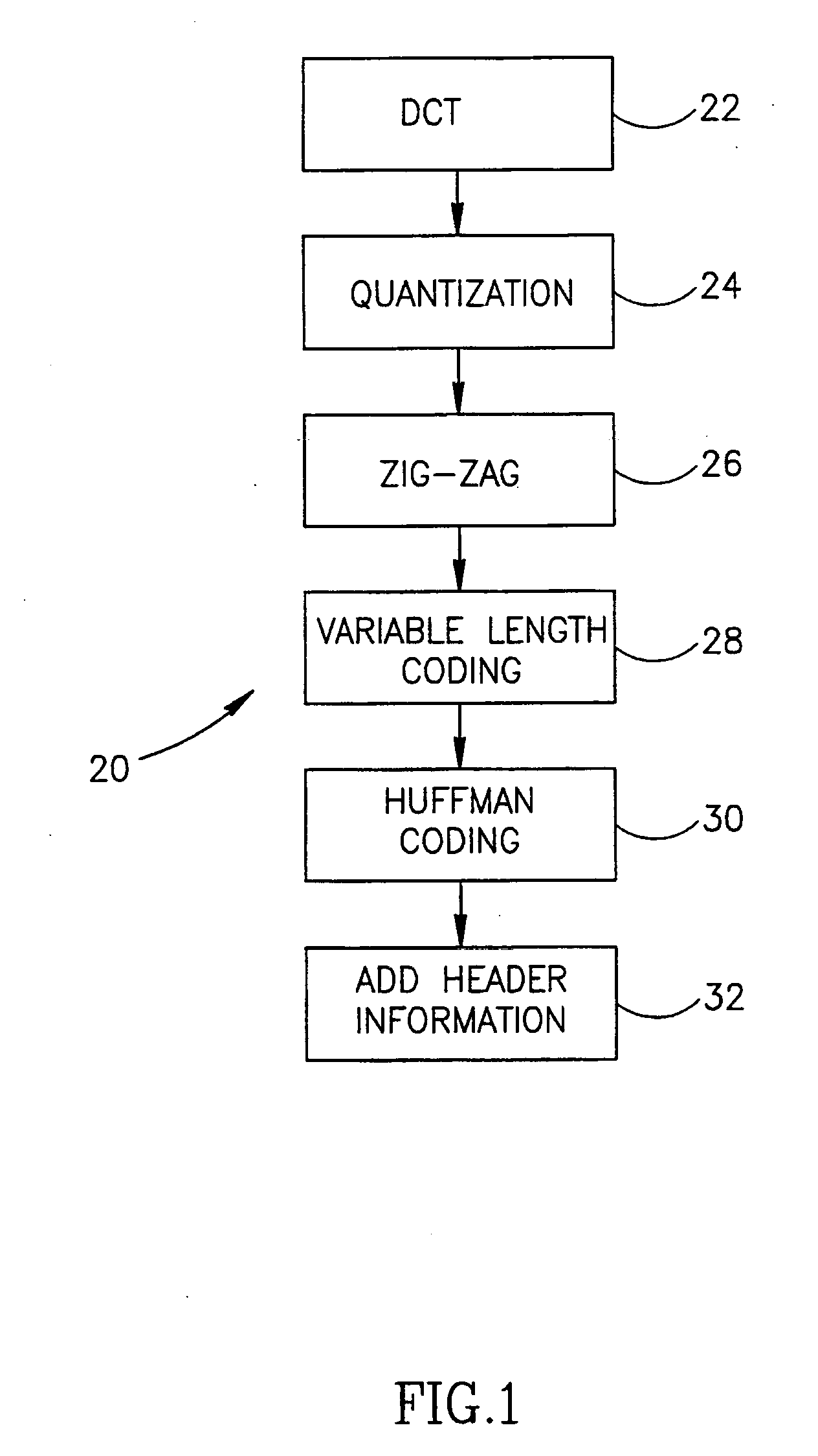
[0074]FIG. 1 is a flowchart of a base-line method 20 of JPEG-compliant compression. Image data is first transformed using the DCT (Discrete Cosine Transform) (22), to generate a set of coefficients. These coefficients are then quantized (24). The quantized coefficients are then unfolded from a 8×8 representation to a 64×1 representation (“Zig-Zag”, 26). These quantized coefficients are encoded using a variable-length encoding scheme (28), zero-run length encoded and then Huffman encoded (30), to reduce entropy. A compressed data file is then generated by prefixing the encoded data with header information (32). Other, similar, methods of JPEG compression are also known.

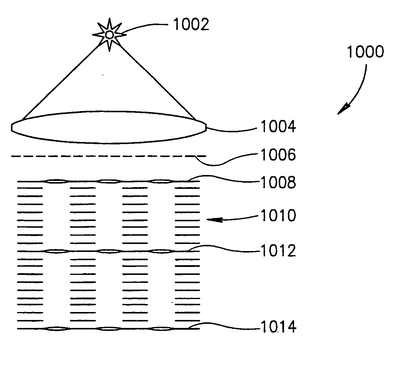
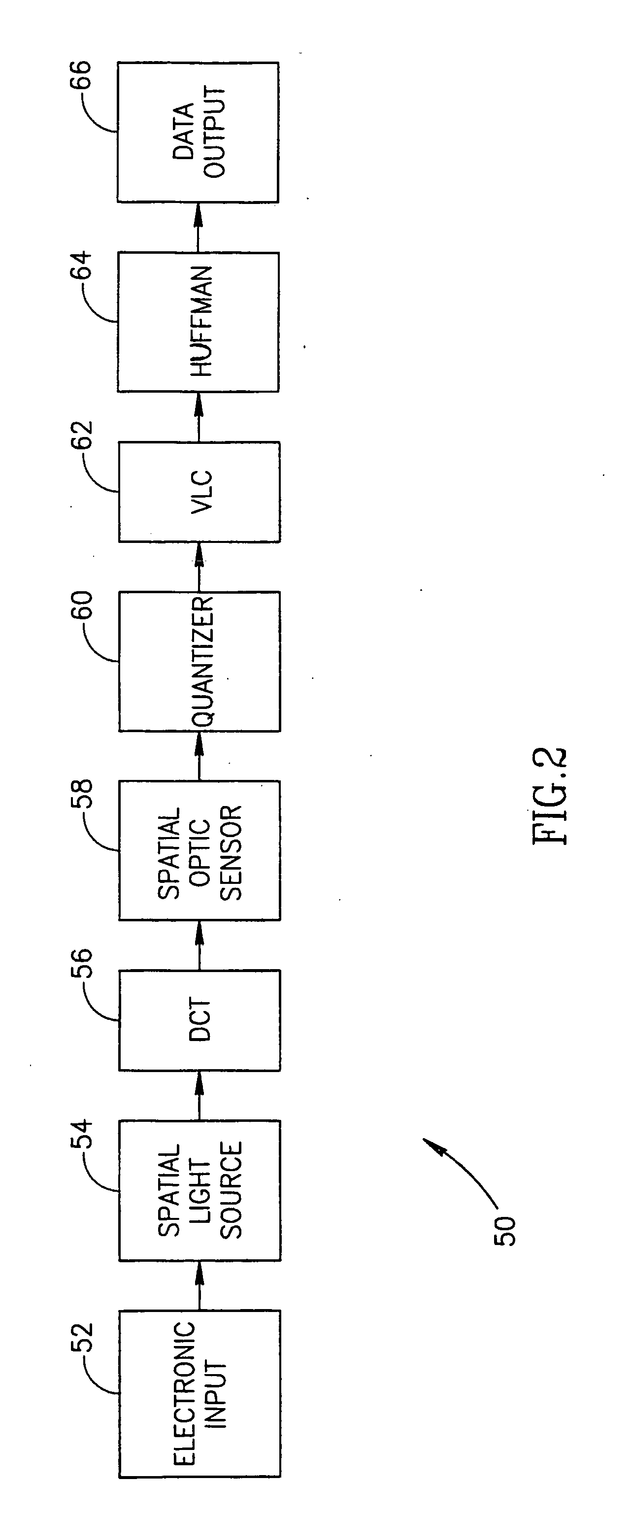
[0075] In accordance with an exemplary embodiment of the invention, various of the above steps are performed using optical elements, rather than using electronic or software elements. In the above described JPEG compression method, the step that is typically most computationally demanding, is the DCT step. Thus, in an...


PUM


Abstract

A method of performing a DFT (discrete Fourier transform) or a DFT derived transform on data, comprising: providing spatially modulated light having spatial coherence, said spatially modulated light representing the data to be transformed; Fourier transforming said spatially modulated light, using an at least one optical element; and compensating for at least one of a scaling effect and a dispersion effect of said at least one optical element, using an at least one dispersive optical element.

Description

RELATED APPLICATIONS [0001] This application is a continuation in part of PCT application PCT / IL99 / 00479, filed Sep. 5, 1999, by applicant Lenslet Ltd. in the IL receiving office and designating the US, the disclosure of which is incorporated herein by reference.FIELD OF THE INVENTION [0002] The present invention relates to the field of optical processing and, in some embodiments, to compressing images using optical components. BACKGROUND OF THE INVENTION [0003] Often, the information bandwidth to be transmitted is greater than the available bandwidth. Therefore, information is often compressed before it is transmitted (or stored), to reduce the required bandwidth. For example, the HDTV standard was defined, at its inception, to include compression. Many types of signals are compressed, including still images, video and telephone conversations. The reigning compression standards are JPEG for still images and MPEG (I, II, III or IV) for video. In actuality, these standards are standa...

Claims


Application Information

Patent Timeline
IPC IPC(8): G02F3/00G02F1/01G06E1/04G06E3/00G06T7/20G06T9/00G06V10/88H04N7/30
CPCG06E3/005H04N19/60G06T7/206G06K9/58G06T7/262G06V10/88
Inventor MENDLOVIC, DAVIDGOLDENBERG, EFRAIMKONFORTI, NAIMZALEVSKY, ZEEVSARIEL, AVIRAM
Owner LENSLET
Why Eureka
Try Eureka