Method for forming a thin-film thermoelectric device including a phonon-blocking thermal conductor

a technology of phonon blockage and thermal conductor, which is applied in the direction of thermoelectric device junction materials, semiconductor devices, semiconductor/solid-state device details, etc., can solve the problems of limited cooling capacity, adversely affecting the performance of these devices, and hardware cos

Inactive Publication Date: 2005-07-14
NANOCOOLERS
View PDF59 Cites 100 Cited by
  • Summary
  • Abstract
  • Description
  • Claims
  • Application Information

AI Technical Summary

Benefits of technology

[0016] In some embodiments, the present invention provides a vertical, monolithic, thin-film thermoelectric device. A thermoelectric device consistent with the present invention may include thermoelectric elements of opposing conductivity types coupled electrically in series and thermally in parallel by associated electrodes on a single substrate, reducing the need for solder joints or other structures or mechanisms to attach

Problems solved by technology

If the heat is not dissipated, it may adversely affect the performance of these devices.
Such passive cooling methods may provide limited cooling capacity due to spatial limitations.
Because of the large required volume, moving mechanical parts, poor reliability and associated cost of the hardware, use of such vapor compression based systems might not be suitable for cooling small electronic devices.
However, unlike conventional vapor compression-based cooling systems, thermoelectric devices have no moving parts.
The lack of moving parts increases reliability and reduces maintenance of thermoelectric cooling devices as compared to conventional cooling systems.
However, typical thermoelectric devices are limited by low efficiency as compared to conventional coolin

Method used


Image

  • Method for forming a thin-film thermoelectric device including a phonon-blocking thermal conductor
  • Method for forming a thin-film thermoelectric device including a phonon-blocking thermal conductor
  • Method for forming a thin-film thermoelectric device including a phonon-blocking thermal conductor

Examples


Embodiment Construction

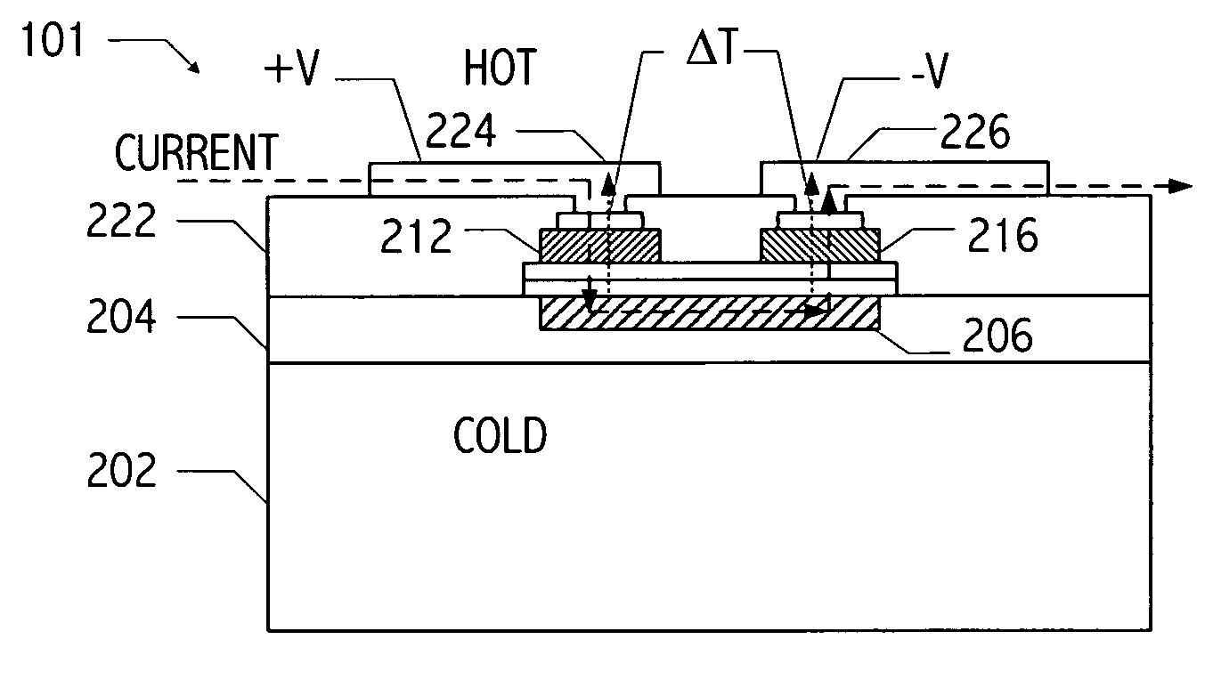
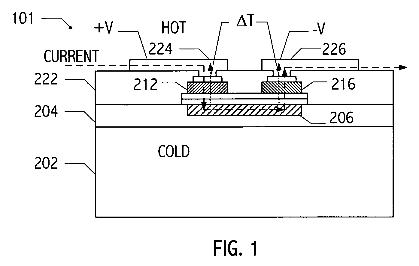
[0051] An exemplary thermoelectric device (thermoelectric device 101 of FIG. 1) includes contacts on a front side (i.e., “top” side) of the structure (e.g., contacts 224 and 226) and a contact thermally coupled to a backside of the structure (e.g. contact 206). As used herein, a contact thermally “coupled” to a backside of the structure may be directly or indirectly coupled to the backside of the structure. In operation, the contacts on the front side of the thermoelectric device have a temperature (e.g., THOT) substantially different from a temperature (e.g., TCOLD) of the contact thermally coupled to the backside of the substrate. The vertical thermoelectric device includes an n-type thermoelectric element and a p-type thermoelectric element (e.g., thermoelectric elements 212, and 216) coupled electrically in series and thermally in parallel. For example, in operation of thermoelectric device 101, a voltage differential is applied between contacts 224 and 226 creating a Peltier ef...


PUM


Abstract

A vertical, monolithic, thin-film thermoelectric device is described. Thermoelectric elements of opposing conductivity types may be coupled electrically in series and thermally in parallel by associated electrodes on a single substrate, reducing the need for mechanisms to attach multiple substrates or components. Phonon transport may be separated from electron transport in a thermoelectric element. A thermoelectric element may have a thickness less than an associated thermalization length. An insulating film between an electrode having a first temperature and an electrode having a second temperature may be a low-thermal conductivity material, a low-k, or ultra-low-k dielectric. Phonon thermal conductivity between a thermoelectric element and an electrode may be reduced without a significant reduction in electron thermal conductivity, as compared to other thermoelectric devices. A phonon conduction impeding material may be included in regions coupling an electrode to an associated thermoelectric element (e.g., a liquid metal).

Description

CROSS-REFERENCE TO RELATED APPLICATION(S) [0001] This application claims the benefit under 35 U.S.C. § 119(e) of U.S. Provisional Application No. 60 / 617,513, filed Oct. 8, 2004, entitled “MONOLITHIC THIN-FILM THERMOELECTRIC DEVICE INCLUDING COMPLEMENTARY THERMOELECTRIC MATERIALS” by Srikanth B. Samavedam, et al., which application is hereby incorporated by reference. [0002] This application is a continuation-in-part of co-pending application Ser. No. 10 / 756,603, filed Jan. 13, 2004, entitled “THERMOELECTRIC DEVICES” by Uttam Ghoshal, which application is hereby incorporated by reference. [0003] This application is related to application Ser. No. ______ (Attorney Docket No. 089-0014), filed on even date herewith, entitled “MONOLITHIC THIN-FILM THERMOELECTRIC DEVICE INCLUDING COMPLEMENTARY THERMOELECTRIC MATERIALS” by Srikanth B. Samavedam, et al.; and application Ser. No. ______ (Attorney Docket 089-0015), filed on even date herewith, entitled “METHOD FOR FORMING A MONOLITHIC THIN-FI...

Claims


Application Information

Patent Timeline
IPC IPC(8): H01L23/38H01L35/12H01L35/30H01L35/34H01L37/00
CPCH01L23/38H01L35/30H01L2924/3011H01L2924/0002H01L2924/00H10N10/13
Inventor SAMAVEDAM, SRIKANTH B.GHOSHAL, UTTAMNGAI, TAT
Owner NANOCOOLERS
Why Eureka
Try Eureka