
Power screwdriver with low-noise torque clutch

Inactive Publication Date: 2005-07-14
HILTI AG
View PDF10 Cites 9 Cited by
  • Summary
  • Abstract
  • Description
  • Claims
  • Application Information

AI Technical Summary

Benefits of technology

[0004] The object of the invention is to provide a power screwdriver with a low-noise torque coupling, which requires a low contact force for activating torque transmission. A further object of the invention is to reduce the quantity of frictional heat in the override operation.
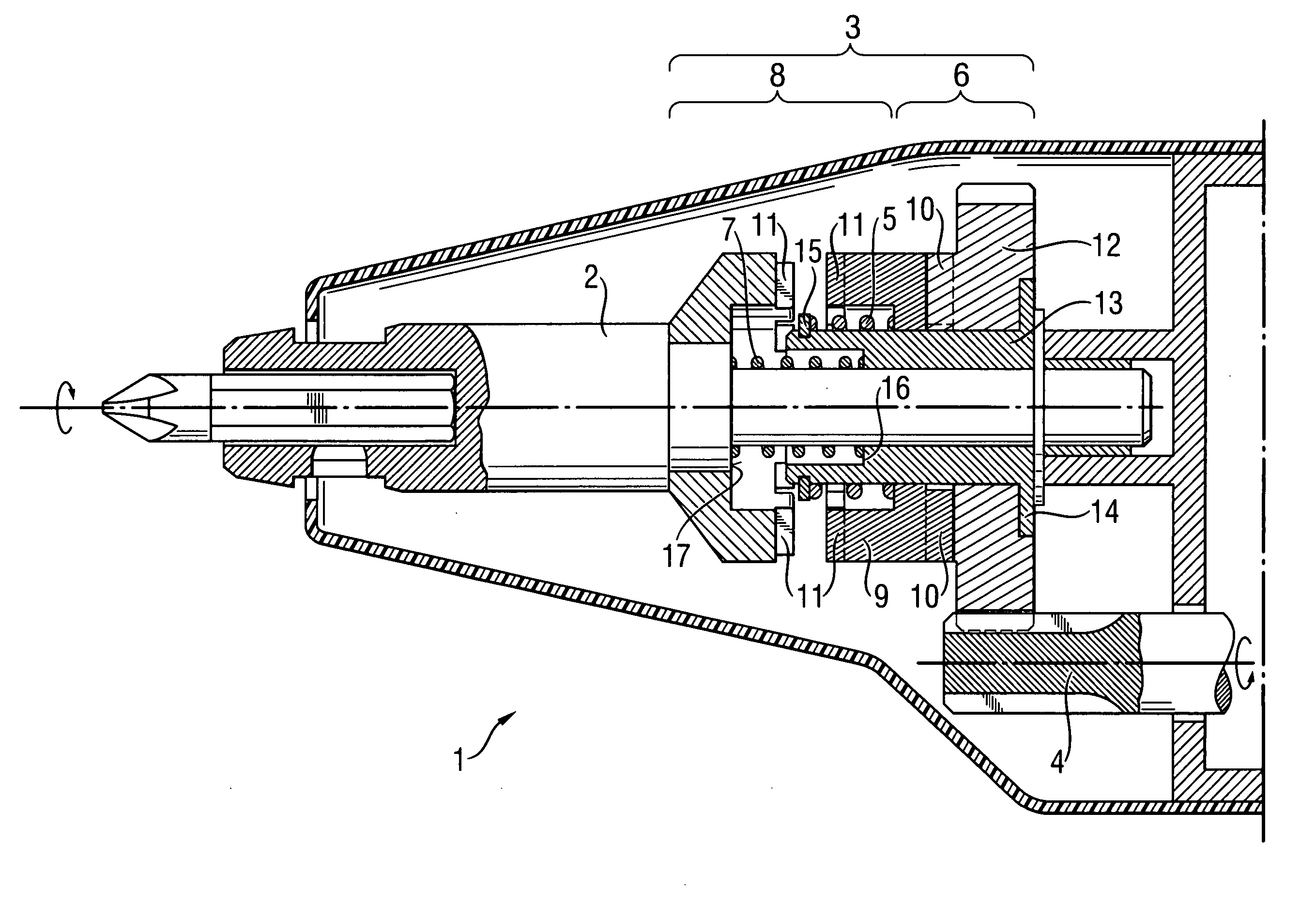
[0006] By virtue of the intermediate sleeve being fixed to the driven ratchet part, the rigid ratchet spring is uncoupled relative to a displacement of the tool spindle. Consequently, upon application of the power screwdriver against the work piece it is not its high spring force that must be overcome but the weak spring force of the slack clutch spring. The quantity of frictional heat of the springs rubbing in override operation is correspondingly lower.
[0008] Advantageously, a locking ring is affixed on the drive-side to the intermediate sleeve, whereby an easily assembled drive-side stop for the ratchet spring is provided.
[0009] Advantageously, the intermediate sleeve has a front open, coaxial inner step on the driving side, whereby a flush, driving-side stop for the clutch spring can be realized in a technologically simple fashion.
[0010] Advantageously, the tool spindle in the axial zone of the claw coupling forms a driving-side radial shoulder, whereby a positive, driving-side stop for the clutch spring can be realized in a technologically simple fashion.

Problems solved by technology

The drawback in this type of simple ratchet coupling is the annoying, loud “chattering”, which also results in increased wear of the ratchet coupling.
In addition, this high contact force results in a high quantity of friction heat in the springs rubbing against each other in the override operation.

Method used


Image

  • Power screwdriver with low-noise torque clutch
  • Power screwdriver with low-noise torque clutch

Examples


Embodiment Construction

[0014] In accordance with the invention, FIG. 1 shows a merely implied power screwdriver 1 with a rotationally driven, axially displaceable mounted tool spindle 2 having a low-noise torque coupling 3, as described more completely in DE 198 44 064. A motor cogwheel 4 driven ratchet coupling 6 that is biased with a rigid ratchet spring 5 is combined with a driving claw coupling 8 that is biased by a slack clutch spring 7. The ratchet coupling 6 is axially combined with the claw coupling using a common, axially displaceable, freely rotational coupling sleeve 9. The ratchet coupling 6 has opposing oriented peripheral inclined beveled cams 10 and the claw coupling 8 has opposing oriented peripheral linear catches 11. A ratchet part 12 driven by the motor cogwheel 4 and the coupling sleeve 9 are arranged freely rotatable on an intermediate sleeve 13, which is mounted freely rotatable and axially displaceable on the tool spindle 2. The ratchet spring 5 is arranged between the intermediate ...


PUM


Abstract

A power screwdriver (1) with a rotationally driven, axially displaceable mounted tool spindle (2) with a low-noise torque clutch (3) which comprises a ratchet-spring biased ratchet coupling (6) driven by a driven ratchet part (12) and a rigid slack clutch spring (7) biased claw coupling (8). The ratchet coupling (6) and the claw coupling (8) are combined using a common, axially displaceable, freely rotatable coupling sleeve (9). The ratchet coupling (6) has opposing oriented, peripheral inclined beveled cams (10) and the claw coupling (8) has opposing oriented catches (11). The driven ratchet part (12) and the coupling sleeve (9) are arranged freely rotatably on an intermediate sleeve (13), which is mounted freely rotatable and axially displaceable on the tool spindle (2). The ratchet spring (5) is arranged between the intermediate sleeve (13) and the coupling sleeve (9) and the clutch spring (7) is arranged between the intermediate sleeve (13) and the tool spindle (2).

Description

BACKGROUND OF THE INVENTION [0001] The invention relates to a power screwdriver having a low-noise torque clutch. In power screwdrivers for driving screws, upon attaining a pre-defined torque the spring force flow from the drive motor to the screw tool is interrupted to avoid excessive driving of the screw. Conventionally, ratchet couplings with two ratchet parts that are spring biased relative to each other are used as torque clutches and each have peripherally inclined beveled cams. The drawback in this type of simple ratchet coupling is the annoying, loud “chattering”, which also results in increased wear of the ratchet coupling. [0002] U.S. Pat. No. 4,655,103 discloses a power screwdriver with a low noise torque clutch, wherein the ratchet coupling is combined with a claw coupling using a common coupling sleeve, wherein a ratchet spring is arranged between the driven ratchet part and the coupling sleeve. [0003] According to U.S. Pat. No. 6,109,149, a power screwdriver has a low-...

Claims


Application Information

Patent Timeline
IPC IPC(8): B25B23/14
CPCB25B23/141
Inventor DONNER, HANS-CHRISTIAN
Owner HILTI AG
Learn More