Sealing method and apparatus for manufacturing high-performance gas discharge panel

a gas discharge panel and high-performance technology, applied in the manufacture of electric discharge tubes/lamps, electrode systems, cold cathode manufacturing, etc., can solve the problems of lcds consuming a small amount of electricity, crts are not suitable for large screen sizes, and the depth and weight increas

Inactive Publication Date: 2005-07-14
PANASONIC CORP
View PDF7 Cites 16 Cited by
  • Summary
  • Abstract
  • Description
  • Claims
  • Application Information

AI Technical Summary

Benefits of technology

[0022] (2) A container whose inside is under a pressure lower than the pressure inside the surrounding unit is used to reduce the pressure inside the surrounding unit.
[0027] It is preferable that the sealing step is performed while the panels are pressurized by fastening tools pinching the panels so that the sealing process is more ensured. In this case, it is further preferable that an anti-deformation member is disposed at a position where the panels are pressurized by the fastening tools so as to prevent the panels from deforming by pressure by the fastening tools.
[0028] It is also preferable that the sealing step is performed while the surrounding unit is provided with anti-displacement means for preventing the relative displacement of the panels. It is further preferable that an anti-sealing-material-inflow member is disposed at the rim of a panel so as to prevent the sealing material from flowing into an inner area of the surrounding unit.

Problems solved by technology

However, the depth and weight increase as the screen size increases.
Therefore, CRTs are not suitable for large screen sizes exceeding 40 inch.
LCDs consume a small amount of electricity and operate on a low voltage.
However, producing a large LCD screen is technically difficult, and the viewing angles of LCDs are limited.
However, the PDPs manufactured with such a method have gaps between the barrier ribs and the front panel.
However, such fastening of the rim tends to generate a gap between the top of the barrier ribs and the front panel at the center by the action of a lever.
In addition, unequal gaps are often formed since the pressures given by the fastening tools are different.
In the PDPs manufactured through the sealing process with such gaps, crosstalks often occur when the PDPs are activated, or noises often occur between the barrier ribs and the panels due to vibration of the panels caused by the discharge or the like.
However, in reality, it is difficult to bond the whole top of the barrier ribs with the front panel.
Accordingly, this technique is not sufficient to solve the problem of the pressure.
Especially, when there are variations of the barrier ribs in height on the back panel, many parts remain unattached.
When this happens, it is impossible to obtain sufficient resistance to pressure.
However, according to this method, more energy is required for the heating since the weight on the panels is also heated.
It is difficult to use this technique for the production of large-screen PDPs.

Method used


Image

  • Sealing method and apparatus for manufacturing high-performance gas discharge panel
  • Sealing method and apparatus for manufacturing high-performance gas discharge panel
  • Sealing method and apparatus for manufacturing high-performance gas discharge panel

Examples


embodiment 1

[0091] In the present embodiment, the sealing process is performed while gas is exhausted from the inner space of the surrounding unit with a vacuum pump.

[0092]FIG. 3 is a sectional view of the sealing apparatus 50 in the present embodiment. FIG. 4 is a perspective view of the sealing apparatus 50 shown in FIG. 3.

[0093] The sealing apparatus 50 is composed of: a furnace 51 for housing and heating the surrounding unit 40 which is the front panel 10 and the back panel 20 put together; and a vacuum pump 52 disposed at outside the furnace 51.

[0094] The furnace 51 is heated by a heater 55. It is possible to set the inner temperature of the furnace 51 to a desired degree with control.

[0095] The sealing process is performed using the sealing apparatus 50 as follows.

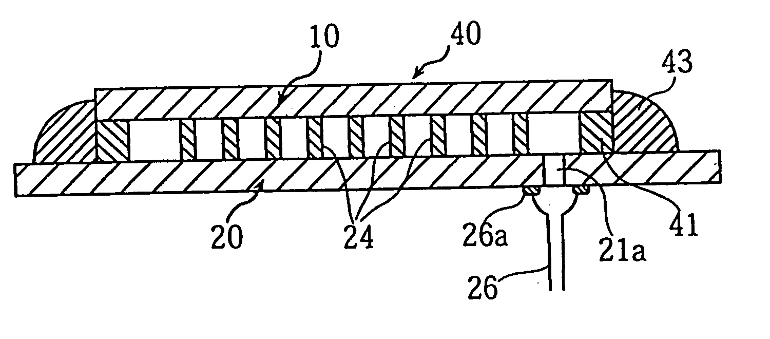
[0096] As shown in FIGS. 3 and 4, an air vent 21a is previously formed in the back panel 20 at the rim, outside the display area.

[0097] A paste mixed with the sealing material is applied to the rim of either of or both the...

embodiment 2

[0125] The present embodiment differs from Embodiment 1 in that after the surrounding unit 40 is formed by positioning the panels 10 and 20 to face each other, in the sealing process, an outer sealing layer 43 is further formed outside the sealing layer 41 formed between the panels 10 and 20 at the rim, as shown in FIGS. 5A and 5B.

[0126] With the above arrangement, if the seal by the sealing layer 41 has a defect, the defect will be covered by the outer sealing layer 43, so that the sealing process is more ensured. In addition, the outer sealing layer 43 reduces the gap between the top of the barrier ribs and the front panel 10.

[0127] Formation of the outer sealing layer 43 provides other effects. For example, the outer sealing layer 43 before softening fixes the panels 10 and 20 and prevents them from being dislocated. Also, a certain degree of hermeticity of the inner space is kept even before the sealing layer 41 or the outer sealing layer 43 softens. As a result, a pressure ca...

embodiment 3

[0130] The present embodiment differs from Embodiment 1 in that an anti-sealing-material-inflow rib 44 is formed inside the area where the sealing layer 41 is to be formed at the rim on either of or both the front panel 10 and the back panel 20, as shown in FIG. 6A.

[0131] By forming the anti-sealing-material-inflow rib 44 beforehand, it is possible to prevent the sealing layer 41 from flowing into the display area when the sealing layer 41 has melted during the sealing process and the pressure inside the surrounding unit 40 has become lower than the pressure outside.

[0132] It is preferable that the anti-sealing-material-inflow rib 44 has about the same height as the barrier ribs 24. This is because: when the rib 44 is higher than the barrier ribs 24, a gap is generated between the front panel 10 and the top of the barrier ribs 24; and when the rib 44 is much lower than the barrier ribs 24, the effect of preventing the inflow of the sealing layer 41 cannot be expected.

[0133] An ea...


PUM


Abstract

A method is provided to steadily produce a gas discharge panel, such as a PDP, in which a panel and the top of the barrier ribs are in intimate contact in entirety. First a surrounding unit for the gas discharge panel is formed, then a process for sealing the surrounding unit with a sealing material inserted between two panels at the rim is performed while pressure is adjusted so that pressure inside the surrounding unit is lower than pressure outside. With this construction, the panels constituting the surrounding unit are bonded together while they are pressurized from outside. As a result, a panel and the top of the barrier ribs on the other panel are bonded together while they are in intimate contact in entirety. To fully acquire these effects, it is preferable that the adjustment of pressure starts before the sealing material hardens. During, before, or after the sealing step, an energy such as laser beams or ultrasonic waves may be radiated onto the top of the barrier ribs to bond a panel and the top of the barrier ribs in entirety almost without a gap between them.

Description

TECHNICAL FIELD [0001] This invention relates to a method for producing a gas discharge panel, more specifically to a process for bonding a front panel and a back panel. BACKGROUND ART [0002] Recently, as the demand for high-quality large-screen TVs such as high definition TVs has increased, displays suitable for such TVs, such as Cathode Ray Tube (CRT), Liquid Crystal Display (LCD), and Plasma Display Panel (PDP), have been developed. [0003] CRTs have been widely used as TV displays and excel in terms of resolution and picture quality. However, the depth and weight increase as the screen size increases. Therefore, CRTs are not suitable for large screen sizes exceeding 40 inch. LCDs consume a small amount of electricity and operate on a low voltage. However, producing a large LCD screen is technically difficult, and the viewing angles of LCDs are limited. [0004] On the other hand, it is possible to make a PDP with a large screen with a short depth, and 50-inch PDP products have alre...

Claims


Application Information

Patent Timeline
Patent Type & Authority Applications(United States)
IPC IPC(8): H01J9/24H01J9/26H01J17/49
CPCH01J9/385H01J9/395H01J9/265H01J2211/36H01J9/261H01J11/10
Inventor SASAKI, YOSHIKINONOMURA, KINZOUHIBINO, JUNICHIYOHEHARA, HIROYUKIYAMASHITA, KATUYOSHIKIRIHARA, NOBUYUKIOOTANI, KAZUOOOKAWA, MASAFUMI
Owner PANASONIC CORP
Why Eureka
Try Eureka