Amplifier apparatus and method

a technology of amplifiers and amplifiers, applied in the direction of amplifiers with semiconductor devices/discharge tubes, differential amplifiers, amplifiers, etc., can solve the problems of insufficient applicability, and achieve the effect of driving large off-chip capacitive loading with little distortion and little distortion

Active Publication Date: 2005-07-14
TEXAS INSTR INC
View PDF3 Cites 0 Cited by
  • Summary
  • Abstract
  • Description
  • Claims
  • Application Information

AI Technical Summary

Benefits of technology

[0008] It is, therefore, an object of the present invention to provide a variable gain amplifier apparatus capable of driving large off-chip capacitive loading with little distortion.
[0009] It is a further object of the present invention to provide a method for buffering a signal with a programmable gain that is appropriate for driving large off-chip capacitive loading with little distortion.

Problems solved by technology

However, such an approach may not suffice when driving a large off-chip capacitance, e.g., on the order of 10 pF.

Method used


Image

  • Amplifier apparatus and method
  • Amplifier apparatus and method
  • Amplifier apparatus and method

Examples


Embodiment Construction

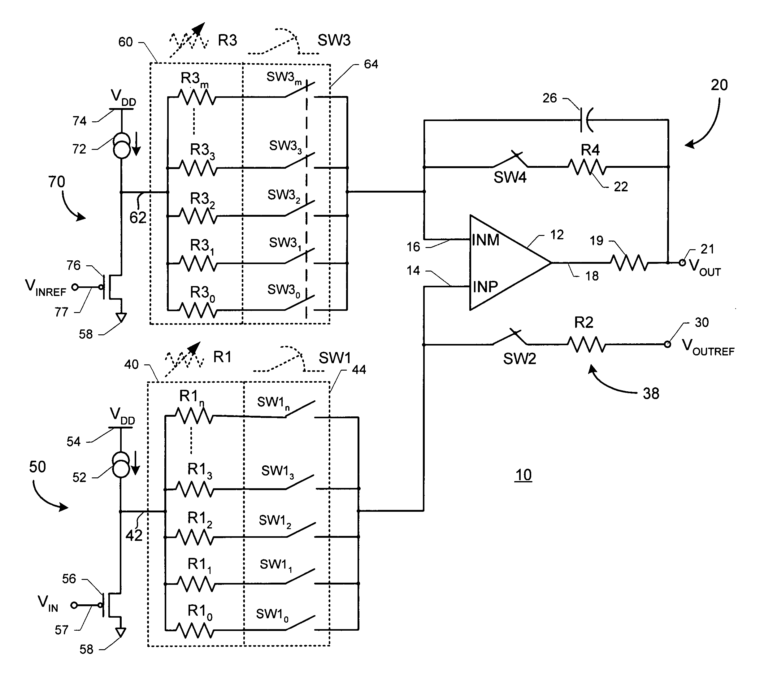
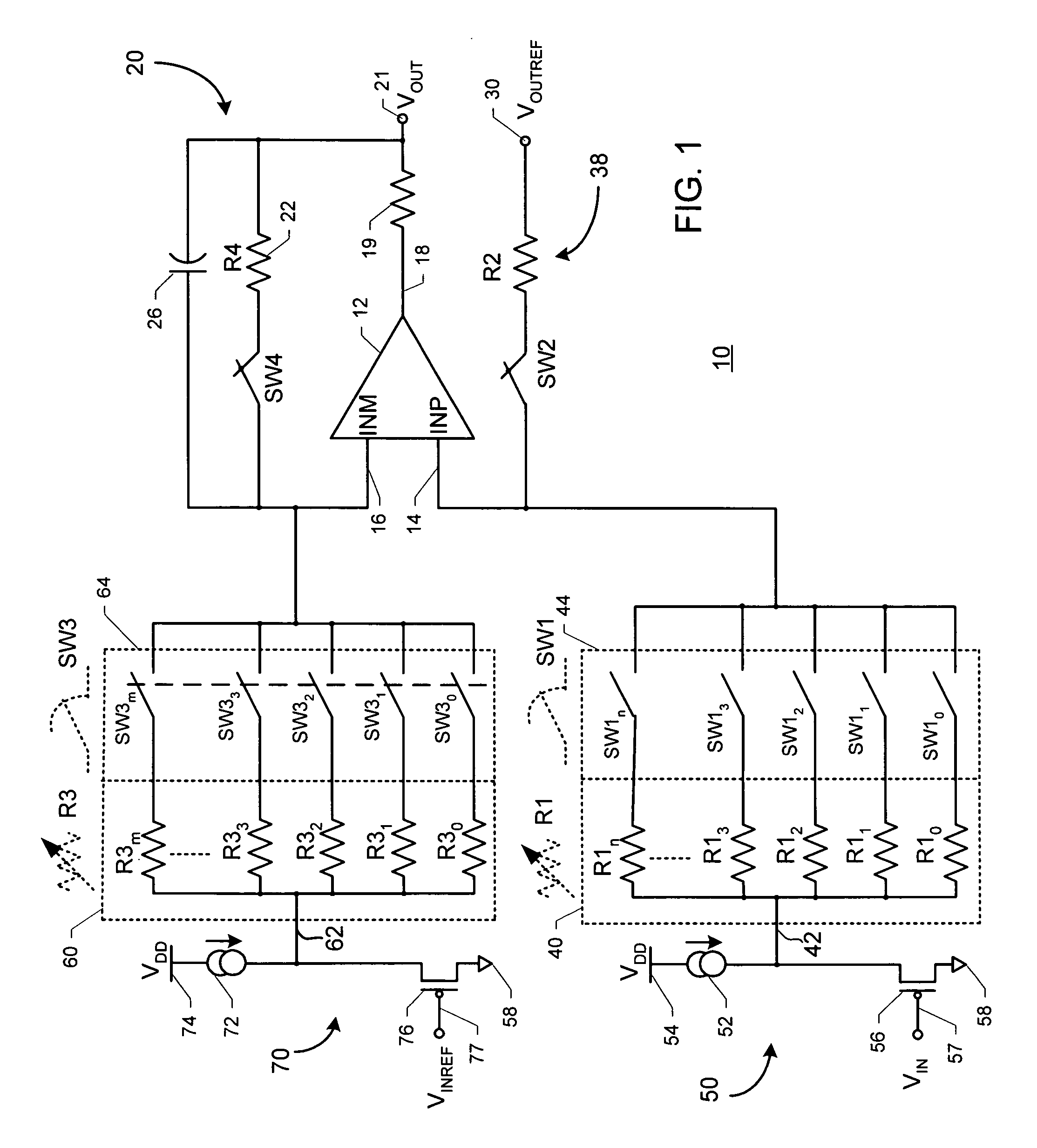
[0013]FIG. 1 is an electrical schematic diagram illustrating the preferred embodiment of the apparatus of the present invention. In FIG. 1, an amplifier apparatus 10 includes an operational amplifier device 12 having a first input locus 14, a second input locus 16 and an output locus 18. A resistor 19 is coupled between output locus 18 and an output signal connector 21. An output signal VOUT is presented at output signal connector 21. A feedback circuit 20 is coupled between output connector 21 and second input locus 16. Feedback circuit 20 includes a resistor R4 connected in series with a dummy always-closed switch SW4. Feedback circuit 20 also includes a capacitor 26 coupled in parallel with resistor R4 and dummy switch SW4.

[0014] A supply circuit 38 is coupled between a signal input connector 30 and first input locus 14. Supply circuit 38 includes a resistor R2 and a dummy always-closed switch SW2. A reference signal VOUTREF is provided at a signal input connector 30. Reference ...


PUM


Abstract

An amplifier apparatus having a gain programmable in discrete increments includes: (a) an operational amplifier having a first and second input and an output; (b) a feedback circuit between the output and the second input; (c) a reference signal source and supply circuit coupled with the first input; (d) a first resistor network coupled between a first signal locus and the first input conveying a first input signal to the first input and including a first plurality of parallel-connected first resistors; selected first resistors being independently coupled in a first connecting with the first input; (e) a second resistor network coupled between a second signal locus and the second input conveying a second input signal to the second input and including a second plurality of parallel-connected second resistors; selected second resistors being independently coupled in a second connecting with the second input.

Description

[0001] This application claims benefit of prior filed copending Provisional Patent Application Ser. No. 60 / 535,276, filed Jan. 9, 2004; and claims benefit of prior filed copending Provisional Patent Application Ser. No. 60 / 537,063, filed Jan. 16, 2004.BACKGROUND OF THE INVENTION [0002] The present invention is directed to electrical amplifier apparatuses, and especially to electrical amplifier apparatuses embodied in programmable gain amplifiers. Programmable gain is a useful feature for an amplifier apparatus for many reasons. An important reason is that a manufacturer may produce a particular model of a product that may be employed by customers for a variety of applications. By producing such multi-use products, a manufacturer may be able to carry fewer individual parts in inventory, and a customer may be able to finely tune a product to provide peak performance in a particular device. [0003] By way of example and not by way of limitation, electrical amplifier apparatuses embodied...

Claims


Application Information

Patent Timeline
Patent Type & Authority Applications(United States)
IPC IPC(8): H03G1/00
CPCH03G1/0088
Inventor XU, GONGGUIBILHAN, HAYDAR
Owner TEXAS INSTR INC
Why Eureka
Try Eureka