Process and device for determining viscosity
- Summary
- Abstract
- Description
- Claims
- Application Information
AI Technical Summary
Benefits of technology
Problems solved by technology
Method used
Image

Examples
first embodiment
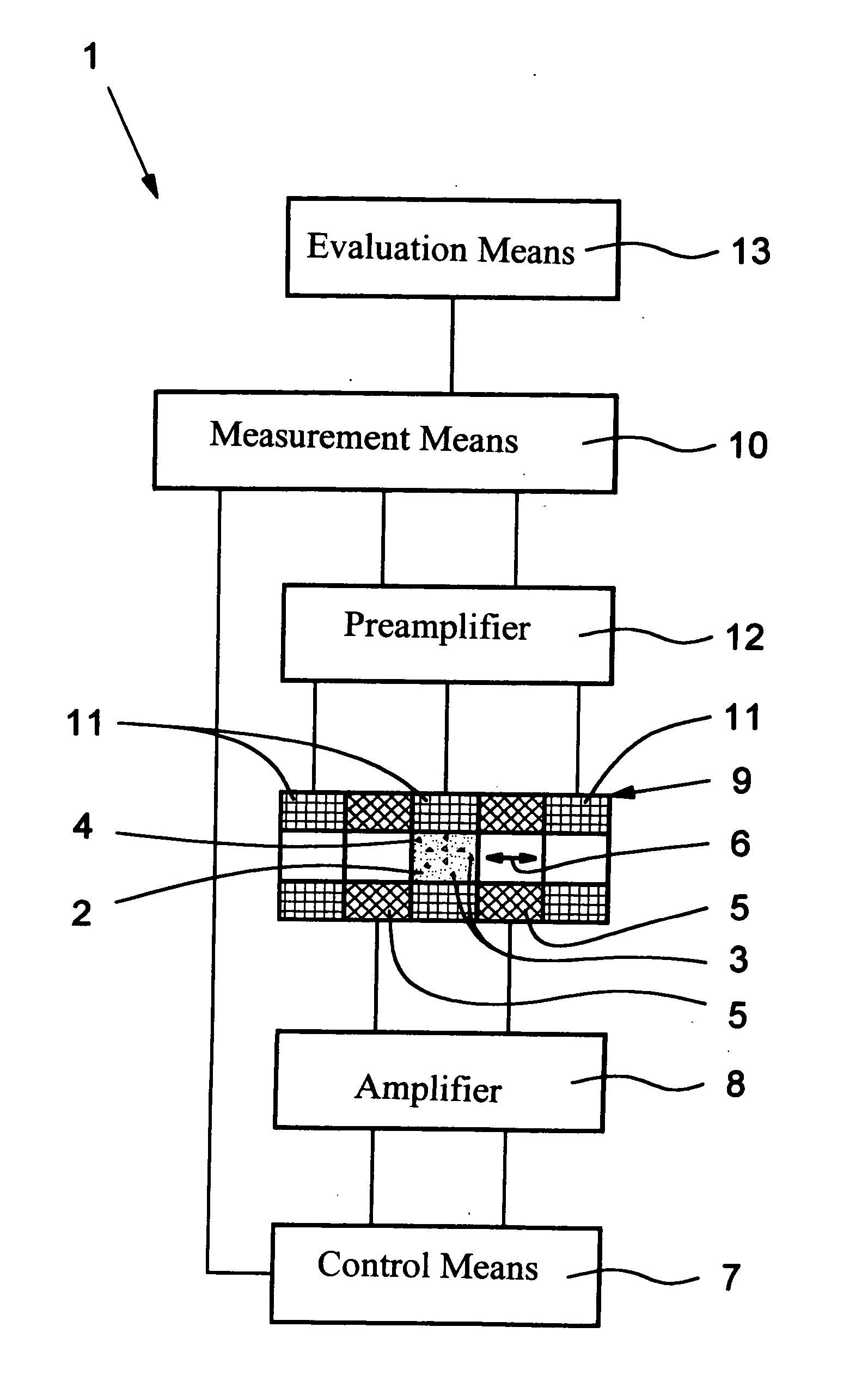
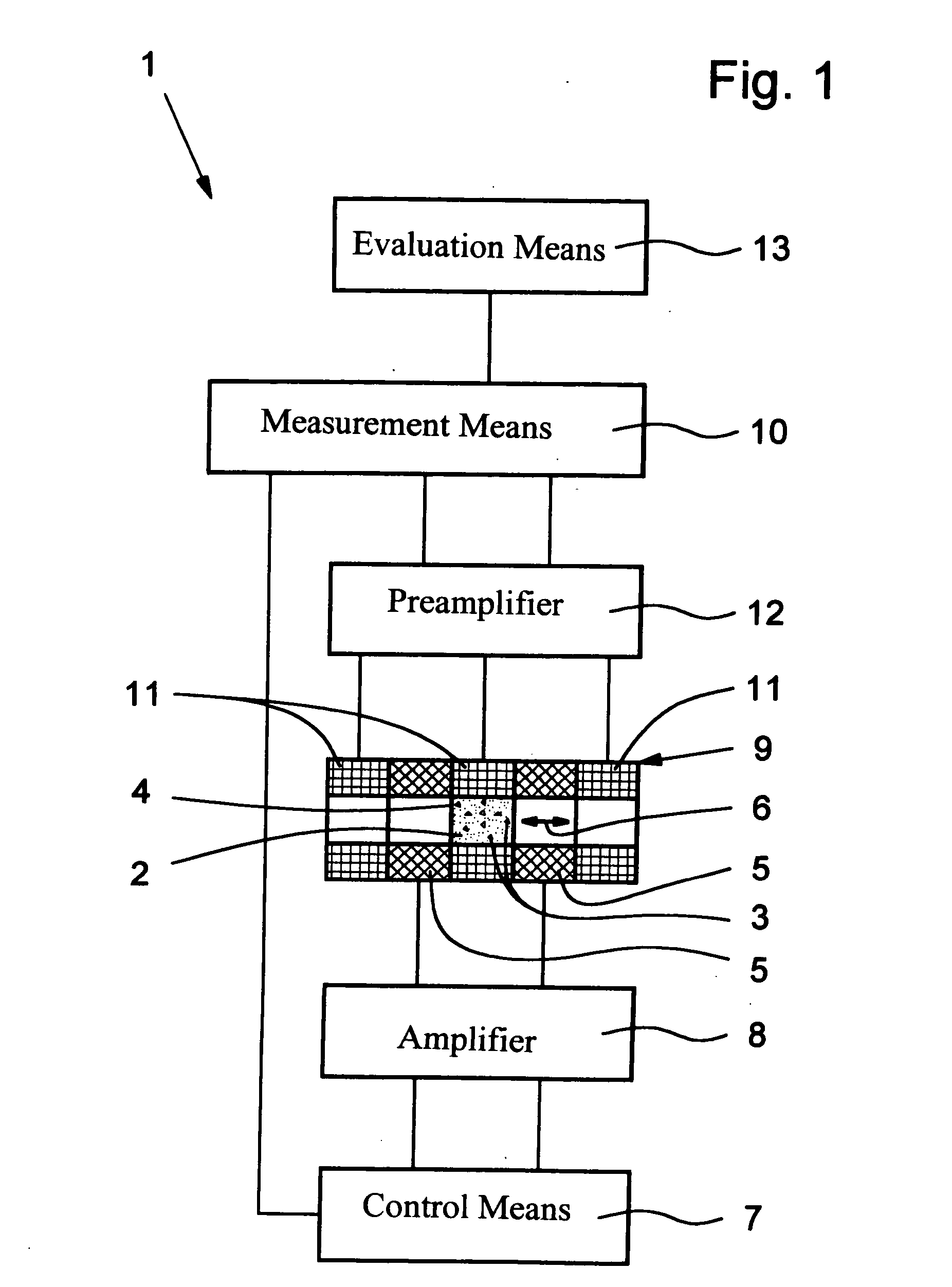
[0025]FIG. 1 shows in a schematic a device 1 as claimed in the invention for determining the viscosity or an associated quantity of a fluid 2.
[0026] The fluid 2 is preferably a liquid, especially for biological or chemical tests or diagnostics.
[0027] The volume of the fluid which is to be measured can be very small and is preferably only in the μl range. In particular it is therefore especially a so-called microfluid.
[0028] The fluid 2 has at least one magnetic particle 3, especially several magnetic particles 3. Several magnetic particles 3 are described each time below. All statements in this respect in general apply accordingly, even if there is only a single particle 3 in the fluid 2.
[0029] Preferably the magnetic particles 3 are added only to the necessary measurement volume of the fluid 2 or only in one area of space or one local measurement area so that the required number of magnetic particles 3 is low. But the particles 3 can also be distributed in the entire fluid 2.
[...
second embodiment
[0065] The detection of particle vibration also takes place by the measurement coils 11 in the They are preferably mutually compensated so that the magnetic field 6 of the coil 5 in the ideal case does not produce a signal in the measurement means 10, especially in its lock-in amplifier or the like.
[0066] In the second embodiment there is preferably only one or two measurement coils 11. The measurement coils 11 are preferably arranged symmetrically to the coil 5 for compensation of the alternating field 6, the measurement coils 11 radially surrounding the measurement chamber 4.
[0067] In place of a measurement coil 11 or the illustrated two measurement coils 11, other sensors can also be used for detection of particle vibration.
[0068] In addition or alternatively to the preamplifier 12, an alternating field impedance bridge for negative feedback in the measurement circuit can be connected to increase the measurement sensitivity.
[0069] In the second embodiment preferably a stronge...
third embodiment
[0077] In the third embodiment the measurement chamber 4 is made in a preferably plate-shaped sample carrier 22. The sample carrier 22 consists preferably of plastic, in which the corresponding cavities are formed. For example it can be a test strip or the like which is used especially for chemical and / or biological diagnostics or microfluidic tests.
[0078] The measurement chamber 4 is preferably made with the main direction of extension running perpendicular to the plane of the plate of the sample carrier 22. The axes of the coil 5 and the magnetic field 6 which varies over time run preferably in the same direction as the measurement chamber 4, therefore here perpendicular to the plane of the plate of the sample carrier 22.
[0079] Therefore the vibration of the magnetic particles 3 takes place preferably at least essentially perpendicularly to the plane of the plate or to the flat sides of the sample carrier 22.
[0080] The device 1 and the sample carrier 22 are preferably made such ...
PUM
 Abstract
Description
Claims
Application Information
PatSnap Eureka turns technology decisions into work you can execute. Powered by our Innovation Knowledge Graph, it runs expert workflows across engineering, life sciences, materials and intellectual property. Get your review-ready output in minutes.


