Electronically controlled throttle control apparatus

a throttle control and electric control technology, applied in the direction of electric control, combustion air/fuel air treatment, machines/engines, etc., to achieve the effect of reducing the rotational load, and reducing the sliding resistance during the relative movement between the rotator and the coil spring

Active Publication Date: 2005-07-21
DENSO CORP
View PDF5 Cites 2 Cited by
  • Summary
  • Abstract
  • Description
  • Claims
  • Application Information

AI Technical Summary

Benefits of technology

[0038] According to the invention set forth in a nineteenth aspect, the rotator is provided with an engaging part for detachably engaging with the U-shaped hook part, and a locking part for locking the other end of the coil spring in the circumferential direction of this engaging part (for example, generally on the same circumference as the engaging part). Consequently, when the U-shaped hook part of the coil spring is mounted on the engaging part of the rotator and the other end of the coil spring is mounted on the locking part of the rotator, it is possible to prevent the rotation of the coil spring and form a cylindrical gap between the spring inner periphery guide integrally formed on the rotator and the coil spring. This allows a further reduction of the sliding resistance during the relative movement between the outer periphery of the spring inner periphery guide of the rotator and the inner periphery of the coil spring.
[0039] According to the invention set forth in a twentieth aspect, the rotator is provided with an engaging part for detachably engaging with the U-shaped hook part, and a locking part for locking the other end of the coil spring in the circumferential direction of this engaging part (for example, generally on the same circumference as the engaging part). Consequently, when the U-shaped hook part of the coil spring is

Problems solved by technology

Consequently, it becomes difficult for the abrasive dust occurring from the member for making sliding contact with the coil spring or the abrasive dust occurring from the coil spring itself because of sliding contact with the member to lie at least in the sliding contact portion between the power transmi

Method used


Image

  • Electronically controlled throttle control apparatus
  • Electronically controlled throttle control apparatus
  • Electronically controlled throttle control apparatus

Examples


third embodiment

[Third Embodiment]

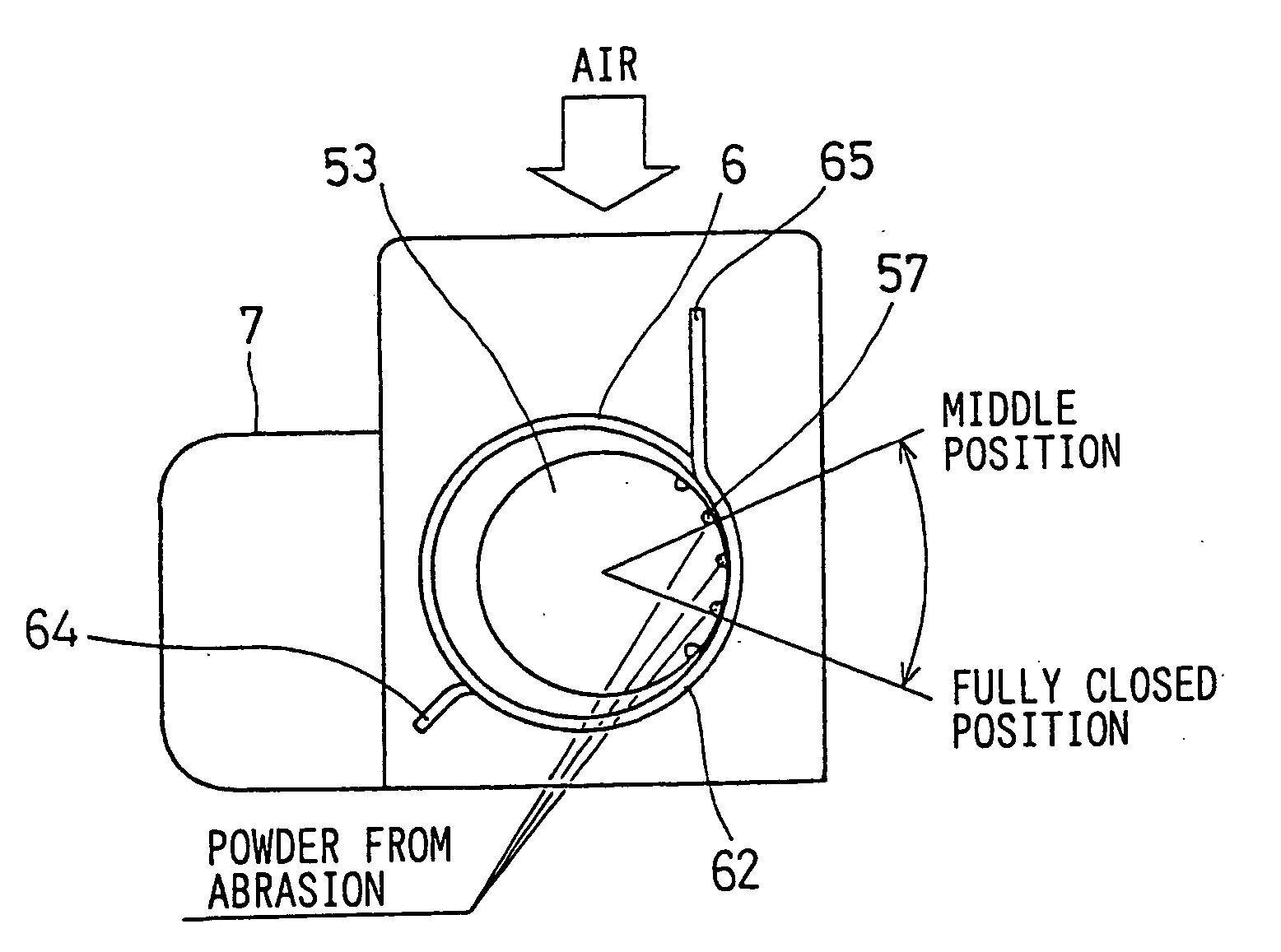
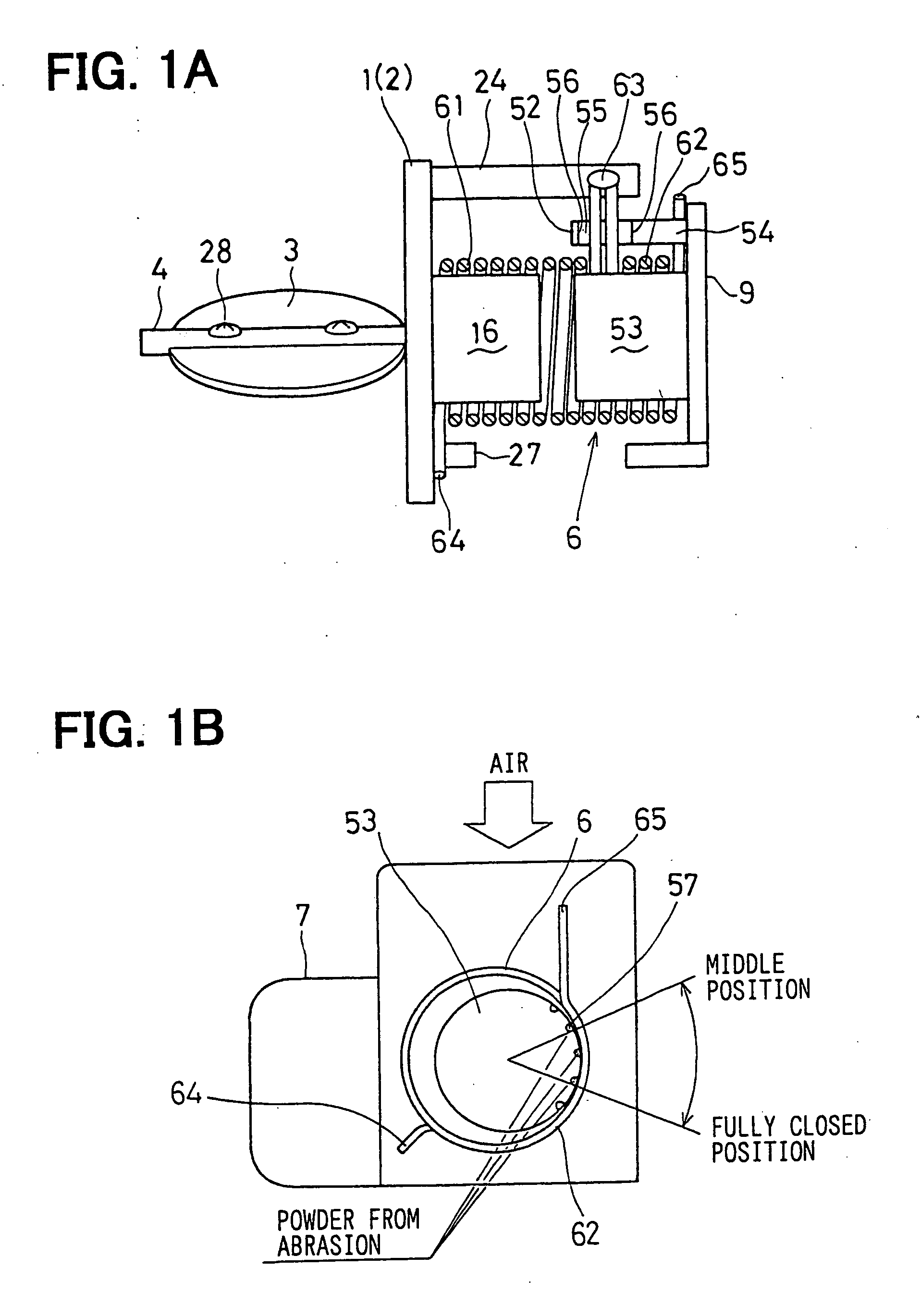
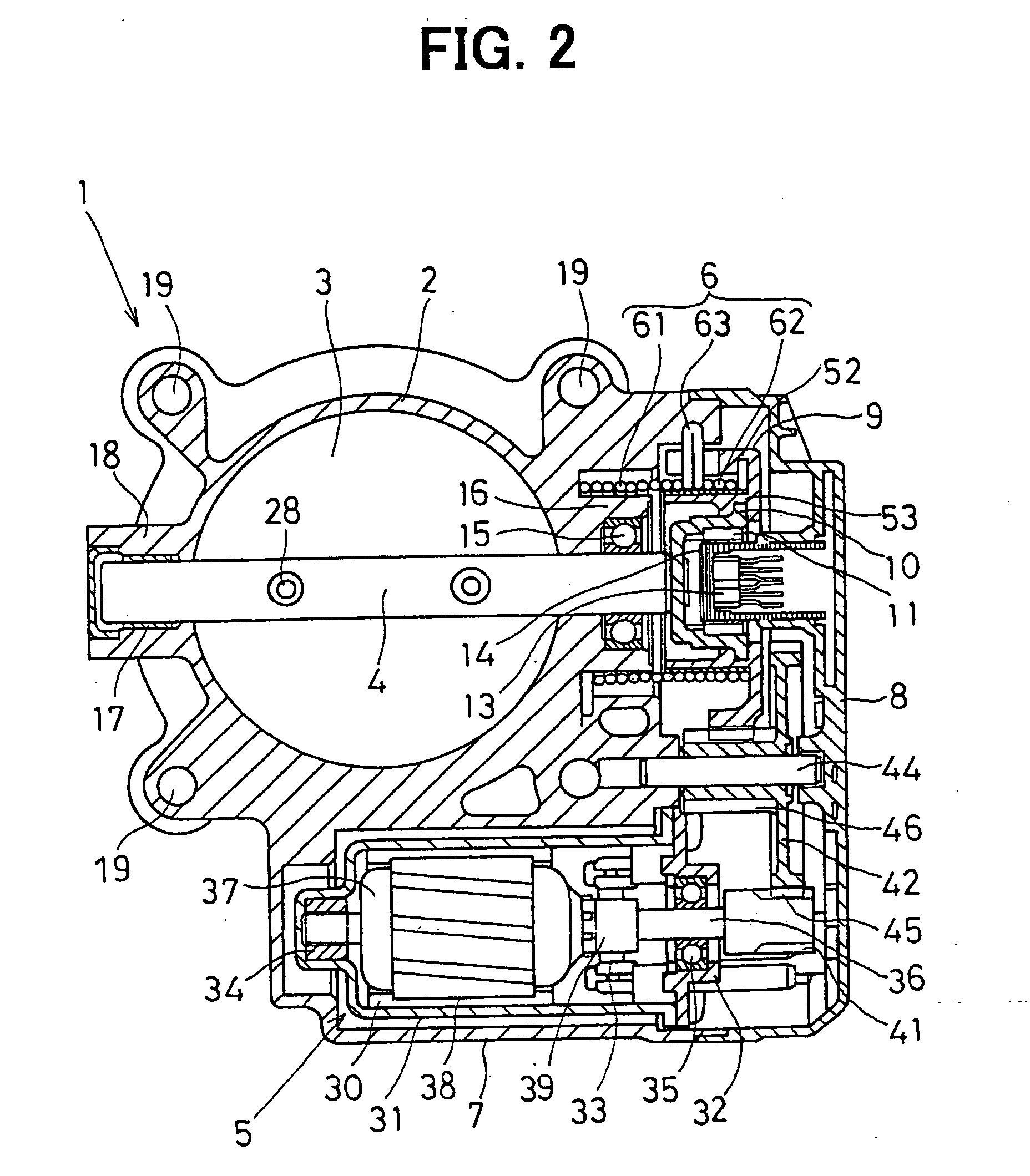
[0154]FIG. 9 is a diagram showing the general structure of an electronically controlled throttle control apparatus, showing a third embodiment of the present invention.

[0155] Like the second embodiment, the present embodiment uses the single coil spring 6 having the coil configuration that the center axis of the default spring 62 is previously decentered in a direction opposite to that of rotational deformation occurring when the other end of the default spring 62 is set to the second locking part (gear-side hook) 54 of the opener member 52 of the valve gear 9 and the U-shaped hook part 63 is set to the engaging part 55 of the opener member 52.

[0156] Then, the spring body-side hook (first part to be locked) 64, which is the one end of the return spring 61 of the single coil spring 6, is locked by the first locking part (body-side hook) 27 of the throttle body 1. In addition, the spring gear-side hook (second part to be locked) 65, which is the other end of the de...

fourth embodiment

[Fourth Embodiment]

[0158]FIGS. 10 and 11 show a fourth embodiment of the present invention. FIG. 10 is a diagram showing a single coil spring and a valve gear. FIG. 11 is a diagram showing the single coil spring.

[0159] In the present embodiment, the other end of the default spring 62 of the single coil spring 6 is extended in an S-shape so as to approach the U-shaped hook part 63, and this S-shaped part makes the spring gear-side hook 65. Then, the spring body-side hook 64, which is the one end of the return spring 61 of the single coil spring 6, is locked by the first locking part 27 of the throttle body 1. In addition, the spring gear-side hook 65 of the default spring 62 of the single coil spring 6 is locked by the second locking part 54 of an opener member 57a of the valve gear 9. Besides, the U-shaped hook part 63 of the single coil spring 6 is engaged with the engaging part 55 which is formed between the anti-sideslip guides 56 of the opener member 52 of the valve gear 9.

[01...

modified examples

[0165] While the present embodiments have dealt with the case where the Hall device 13 is used as the detecting device of a noncontact type, a Hall IC, a magneto-resistive device, or the like may be used as the detecting device of noncontact type. Moreover, while the present embodiments have dealt with the case where the permanent magnets 11 of split type are used as the magnetic field generating source, a permanent magnet of cylindrical shape may be used as the magnetic field generating source.

[0166] Incidentally, the single coil spring 6, i.e., the return spring (first spring part) 61 or the default spring (second spring part) 62, or the default spring (second spring part) 62 in particular, may be a regular pitch coil having a coil outside diameter generally constant in the direction of the center axis and a constant coil pitch, a variable pitch coil having a coil outside diameter generally constant in the direction of the center axis and varying coil pitches, or a nonlinear spri...


PUM


Abstract

An electronically controlled throttle control apparatus prevents a throttle valve from malfunctioning due to deterioration in sliding resistance ascribable to abrasive dust at a sliding contact portion between a valve gear of a geared reduction device and a coil spring. The outer periphery of a spring inner periphery guide is provided with a plurality of groove portions as abrasive dust removing means for removing abrasive dust at least from a sliding contact portion between the outer periphery of the spring inner periphery guide and the inner periphery of a default spring, so that individual edge portions of the plurality of groove portions can rub the inner periphery of the default spring to scrape off abrasive dust from the inner periphery of the default spring and direct the abrasive dust into the plurality of groove portions.

Description

CROSS REFERENCE TO RELATED APPLICATIONS [0001] This application is based upon, claims the benefit of priority of, and incorporates by reference Japanese Patent Application No. 2003-61305 filed Mar. 7, 2003, No. 2003-74432 filed Mar. 18, 2003, and No. 2003-426955 filed Dec. 24, 2003. FIELD OF THE INVENTION [0002] The present invention relates to an electronically controlled throttle control apparatus for controlling the amount of intake air into an internal combustion engine by adjusting the valve opening of a throttle valve through the operation of a drive motor. BACKGROUND OF THE INVENTION [0003] Conventionally, there have been proposed electronically controlled throttle control apparatuses which have an opener side function of mechanically holding a throttle valve in a predetermined intermediate position between a fully-closed position and a fully-open position by utilizing respective different biasing forces of a plurality of springs when the supply of an electric current to a dr...

Claims


Application Information

Patent Timeline
IPC IPC(8): F02D9/02F02D9/10F02D11/10
CPCF02D9/1065F02D11/10F02D11/107F16K31/563F02D2009/0294F16F1/12F16K1/221F02D2009/0267
Inventor TANIMURA, HIROSHIUEHAMA, MOTOKIKAMIYA, AKIHIROARAI, MASATO
Owner DENSO CORP
Why Eureka
Try Eureka