Light emitting device

a light-emitting device and light-emitting technology, which is applied in the direction of luminescent compositions, discharge tubes/lamp details, chemistry apparatus and processes, etc., can solve the problems of insufficient red components of light-emitting devices, difficult to obtain multi-color light-emitting devices, and insufficient light-emitting devices, etc., to achieve excellent color rendering properties and a wide range of color tones

Active Publication Date: 2005-07-21
NICHIA CORP
View PDF14 Cites 173 Cited by
  • Summary
  • Abstract
  • Description
  • Claims
  • Application Information

AI Technical Summary

Benefits of technology

[0037] In the light emitting device of the present invention, emission of white light can be easily achieved when the device has two or more emission peaks in the visible light region and wavelengths of at least two of the two or more emission peaks are in complementary color relation with each other. Here white color includes (purplish) white, (bluish) white, (greenish) white, (yellowish) white, (light) pink, as well as (light) violet, (light) blue violet, (light) blue, (light) blue green, (light) green, (light) yellow green, (light) yellow, (light) yellow red, (orangish) pink, pink and (purplish) pink.
[0038] In the light emitting device of the present invention, general color rendering index (Ra) can be set to 80 or higher and can be maintained at 80 or higher even when the drive current density of the light emitting element fluctuates. In the light emitting device of the present invention, general color rendering index (Ra) can be maintained at 80 or higher, for example, when the drive current density of the light emitting element changes from 2.0 A / cm2 to 50.0 A / cm2. Special color rendering index (R9), in particular, is preferably 50 or higher. This enables it to provide a light emitting device having broad range of color tones, as well as light emitting device of excellent color rendering property. General color rendering index (Ra) is the special color rendering index averaged over eight test color chips No.1 to No.8, specified in CIE and JIS.

Problems solved by technology

There is a problem, in particular, that light emitted by such a device has insufficient red component and a low value of special color rendering index R9 that represents red component.
There is also such a problem that, since the device can emit light of only such colors that lie on a line connecting blue and the color of light emitted by YAG material on the chromaticity diagram, it is difficult to obtain light of a desired color by adjusting the amounts of fluorescent materials, namely it is difficult to obtain a multi-color light emitting device.
A light emitting device that employs a light emitting element which emits ultraviolet ray such as that described in Patent Document 1 has low intensity of emitted light at wavelengths around 500 nm, resulting in low color rendering property.
But these attempts have been facing such a problem that difference in the excitation characteristics among the fluorescent materials results in color deviation and / or variation in the color rendering property.

Method used


Image

  • Light emitting device
  • Light emitting device
  • Light emitting device

Examples


first embodiment

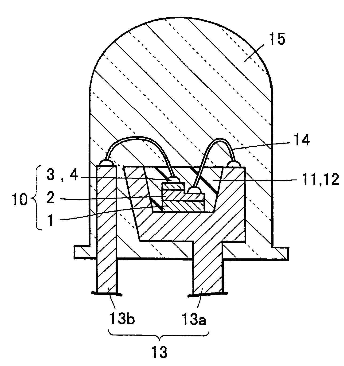
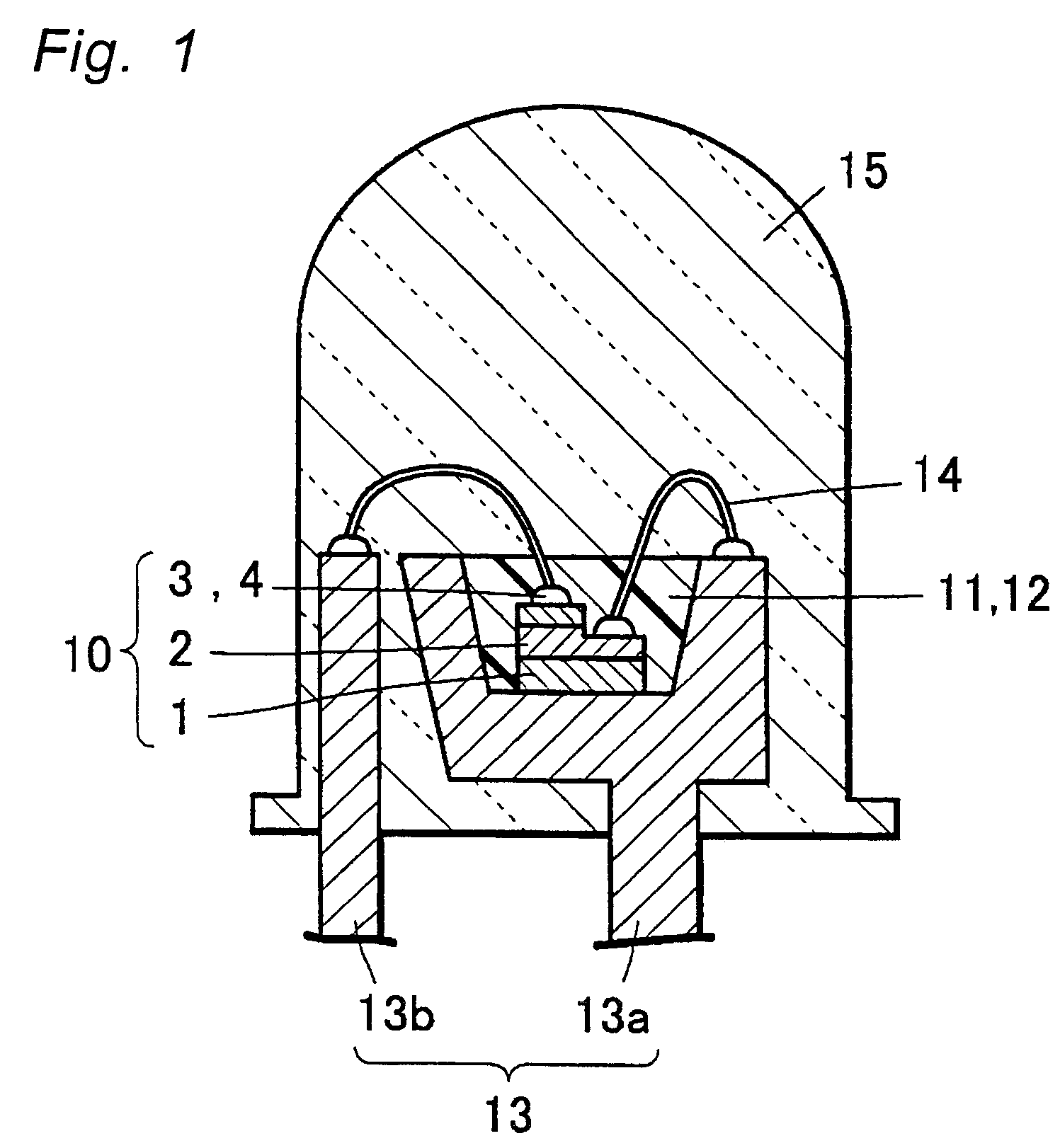
[0104] The light emitting device according to the first embodiment of the present invention uses an excitation light source that emits light in ultraviolet to blue region and two or more kinds, preferably three or more kinds of fluorescent material that are substantially directly excited by the light emitted by the excitation light source and emit light, so as to generate light of various colors through blending of the light emitted by these fluorescent materials. The light emitting device of this embodiment is particularly characterized in that all the fluorescent materials have luminescence center of direct transition type thereby suppressing both the variation in the color of emitted light (color deviation) due to variation in the drive current of the light emitting element and the variation in the color of emitted light due to difference in the drive mode (particularly the difference between DC drive and pulse drive) to extremely low levels. A specific example of the light emitt...

second embodiment

[0187] The light emitting device according to the second embodiment of the present invention is a variation of the light emitting device according to the first embodiment where a blue light emitting element is used as light emitting element and yttrium aluminum garnet fluorescent material (YAG fluorescent material) is used as the second fluorescent material. This embodiment is similar to the first embodiment with other respect.

[0188] The light emitting device of the second embodiment uses a blue light emitting element that emits blue light (for example, wavelength 460 nm) and at least two kinds of fluorescent material which are excited by the blue light and emit light of longer wavelengths, so as to generate light of desired color through blending of the blue light from the light emitting element and the light from the fluorescent materials.

[0189] The light emitting device according to the second embodiment of the present invention constituted as described above suppresses both th...

third embodiment

[0200] In this embodiment, an excitation light source having principal emission peak wavelength in a range from 250 nm to 500 nm is used, and two or more kinds of fluorescent material that are directly excited by the excitation light source containing oxynitride-based fluorescent material or nitride-based fluorescent material are used. This embodiment is similar to the first embodiment, except for the difference described below.

[0201] Both oxynitride-based fluorescent material and nitride-based fluorescent material can be of the direct excitation type. As a result, in this embodiment, too, the variation in the color of emitted light (color deviation) due to variation in the drive current of the light emitting element and the variation in the color of emitted light due to difference in the drive mode (particularly the difference between DC drive and pulse drive) can be suppressed to extremely low levels, by using two or more kinds of fluorescent material of direct transition type si...


PUM

PropertyMeasurementUnit
color rendering indexaaaaaaaaaa
luminous intensityaaaaaaaaaa
wavelengthsaaaaaaaaaa

Abstract

A light emitting device that emits light of various colors by blending lights emitted by two or more kinds of fluorescent materials which are substantially directly excited by the light emitted by an excitation source having principal emission peak in a range from 250 nm to 500 nm. Each of the fluorescent material is of a direct-transition type.

Description

BACKGROUND OF THE INVENTION [0001] 1. Field of the invention [0002] The present invention relates to a light emitting device that uses a light emitting element and fluorescent material, and can be used for such applications as signal light, illumination, display, indicator and other light sources, and particularly to a light emitting device that can emit light of white and other color tones by using fluorescent material that is excited by the light emitted by a light emitting element, which emits in ultraviolet to visible light region, and emits light in the visible light region. [0003] 2. Description of the Related Art [0004] Various light emitting diodes (LED) and laser diodes (LD) have been developed as light emitting elements. These light emitting elements are replacing part of electric bulbs and cold cathode ray tubes that are used as light sources for display, back light and indicator, etc. by taking advantage of such features as the capability to run on low voltage, compact c...

Claims


Application Information

Patent Timeline
Patent Type & Authority Applications(United States)
IPC IPC(8): C09K11/08C09K11/56C09K11/59C09K11/61C09K11/63C09K11/64C09K11/73C09K11/77C09K11/80H01J1/00H01L33/06H01L33/32H01L33/50H01L33/54H01L33/56H01L33/60H01L33/62H05B33/14
CPCC09K11/0883H01L2224/73265C09K11/7731C09K11/7734C09K11/7736C09K11/7739C09K11/774C09K11/7774C09K11/7789C09K11/7797H01L33/502H01L33/504H05B33/14H01L2224/45139H01L2224/45144C09K11/565H01L2224/49107H01L2224/48257H01L2224/48247H01L2224/48091H01L2924/00014H01L2924/00H01L2924/181C09K11/77347H01L2924/00012H01L2224/45015H01L2924/207
Inventor TAKASHIMA, SUGURUKAMESHIMA, MASATOSHITAMAKI, HIROTOTAKEICHI, JUNJIMURAZAKI, YOSHINORIKINOSHITA, SHINPEI
Owner NICHIA CORP
Why Eureka
Try Eureka