Microstrip antenna having mode suppression slots

Inactive Publication Date: 2005-07-21
THE UNITED STATES OF AMERICA AS REPRESENTED BY THE SECRETARY OF THE NAVY
View PDF8 Cites 8 Cited by
  • Summary
  • Abstract
  • Description
  • Claims
  • Application Information

AI Technical Summary

Benefits of technology

[0007] The present invention overcomes some of the difficulties of the past in that comprises a highly effective TM microstrip antenna for suppressing unwanted modes of operation which occur in the GPS L-1 band of 1.575 GHz±10 MHz and substantially reduce noise radiated by the TM microstrip antenna at GPS L-1 band.
[0008] The TM microstrip antenna comprising the present invention includes a copper patch, and a dielectric substrate upon which the copper patch is mounted. The TM microstrip antenna also has a pair of elongated slots which are orientated in the direction of surface current flow on the c

Problems solved by technology

A problem occurs when the microstrip antenna is designed to radiate at one mode of op

Method used


Image

  • Microstrip antenna having mode suppression slots
  • Microstrip antenna having mode suppression slots
  • Microstrip antenna having mode suppression slots

Examples


Embodiment Construction

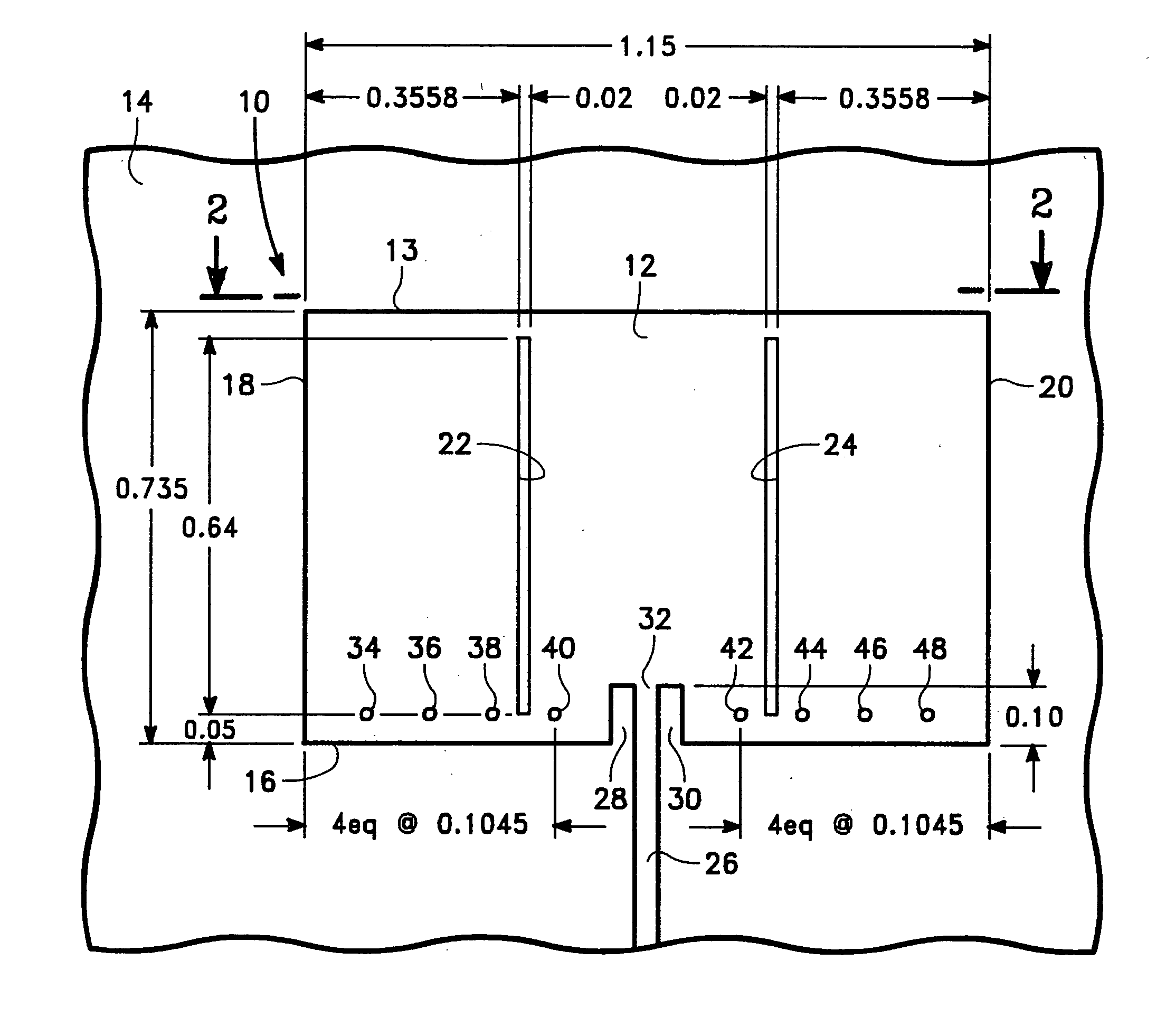
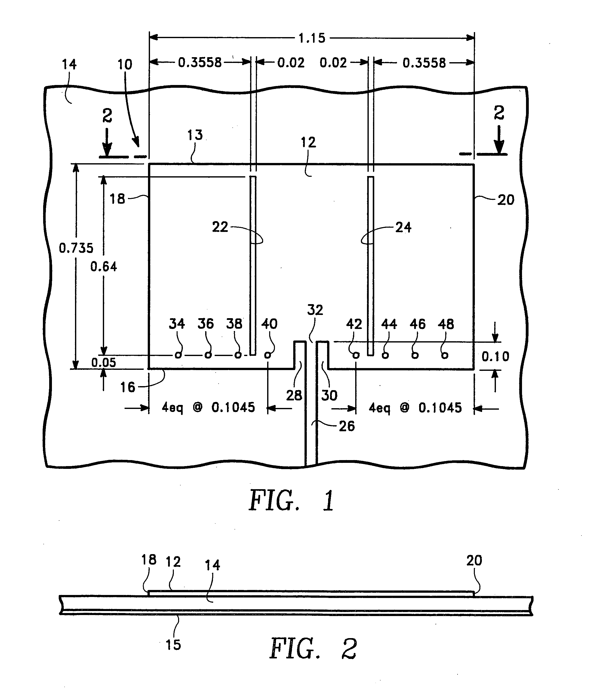
[0014] Referring first to FIGS. 1 and 2, there is shown a TM microstrip antenna 10 for transmitting telemetry data via an RF carrier signal to a receiving station. TM microstrip antenna operates in the telemetry band (TM band) at a center frequency of 2.25 GHz. TM microstrip antenna 10 has linear polarization which is achieved by the copper patch / antenna element 12 depicted in FIG. 1. The bandwidth for TM microstrip antenna 10 is ±10 MHz.

[0015] Microstrip antenna 10 includes copper patch / antenna element 12, a dielectric substrate 14 which has the antenna element 12 mounted on its upper surface and a ground plane 15 which is positioned below the dielectric substrate 14 as shown in FIG. 2. The dielectric substrate 14 used in the preferred embodiment of the present invention has a thickness of 0.050 inches and is fabricated from a laminate material RT / Duroid 6002 which is commercially available from Rogers Corporation of Rogers, Conn. The dielectric material selected for the microstri...


PUM


Abstract

A TM microstrip antenna which having a pair of mode suppression slots for transmitting telemetry data to an external source, which is adapted for use in a small area on a weapons system such as a missile. The mode suppression slots reduce noise from the TM microstrip antenna at the GPS L-1 band providing increased isolation between the TM microstrip antenna and a GPS receiving antenna mounted in proximity to the TM microstrip antenna.

Description

BACKGROUND OF THE INVENTION [0001] 1. Field of the Invention [0002] The present invention relates generally to a microstrip antenna for use on a weapons system to transmit telemetry data from the weapons system. More specifically, the present invention relates to a microstrip antenna which has mode suppression slots and which is adapted for use on a weapons system such as a missile. [0003] 2. Description of the Prior Art [0004] There is currently a need for a microstrip antenna for use in a small diameter projectile and for transmitting telemetry data while suppressing unwanted modes of operation. Normally, microstrip antennas exhibit many modes of operation, that is microstrip antennas will work at multiple frequencies depending upon their construction. A problem occurs when the microstrip antenna is designed to radiate at one mode of operation and not at a frequency band that is outside of the desired mode of operation. [0005] For the desired mode of operation which is 2.250 GHz, ...

Claims


Application Information

Patent Timeline
IPC IPC(8): H01Q9/04
CPCH01Q9/0442H01Q9/0421
Inventor RYKEN, MARVIN L. JR.DAVIS, ALBERT
Owner THE UNITED STATES OF AMERICA AS REPRESENTED BY THE SECRETARY OF THE NAVY
Why Eureka
Try Eureka