[0028] The
advantage of the present invention is that by setting the control input
signal P, a compromise between the retrieved / reconstructed
image quality (large number of texels used), on the one hand, and the
processing speed (small number of texels used), on the other hand, may be achieved. A benefit of limiting the boundary edges is that the hardware expense required for further
processing of the footprint in subsequent processes may be significantly reduced. Such subsequent processes include, for example, determining the texels overlapped by the footprint and / or weighting these specific texels. By clamping the edge lengths, the hardware expense associated with these process steps may be clearly reduced.
[0029] In general, the data produced by the inventive method may be provided to every
texel-oriented raster process.
[0030] In accordance with a preferred embodiment of the present invention, a plurality of so-called image maps having various resolutions, which image maps are also referred to as mipmaps, are provided for a texture associated with the footprint, as has already been described above. In order to specify the resolution, the size of the texels in a
texel grid which are touched by the footprint is determined in dependence on the dimension or shape of the footprint and in dependence on a desired
image quality of the footprint to be represented. Depending on the
texel size thus determined it is established whether there exists, among the plurality of image maps, an
image map whose associated texel size matches the texel size established. If this is so, the respective
image map is employed for representing the footprint. If there is no such respective
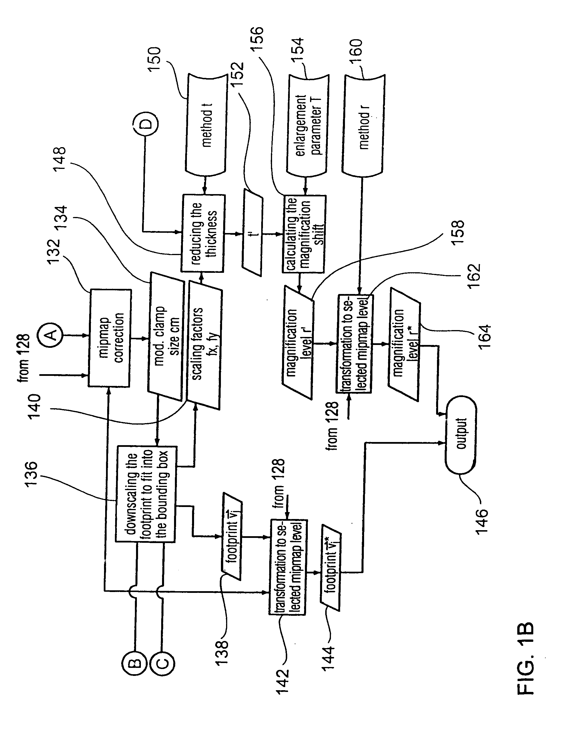
image map, however, the size of the footprint is reduced as has been described above, so that, depending on the
image quality of the footprint, an available image map having a resolution which is one down from the desired resolution and having a respective texel size is selected for representing the footprint.
[0031] Preferably, the image quality is specified by the performance parameter C essentially indicating the number of texels in a texel grid which are touched by the footprint.
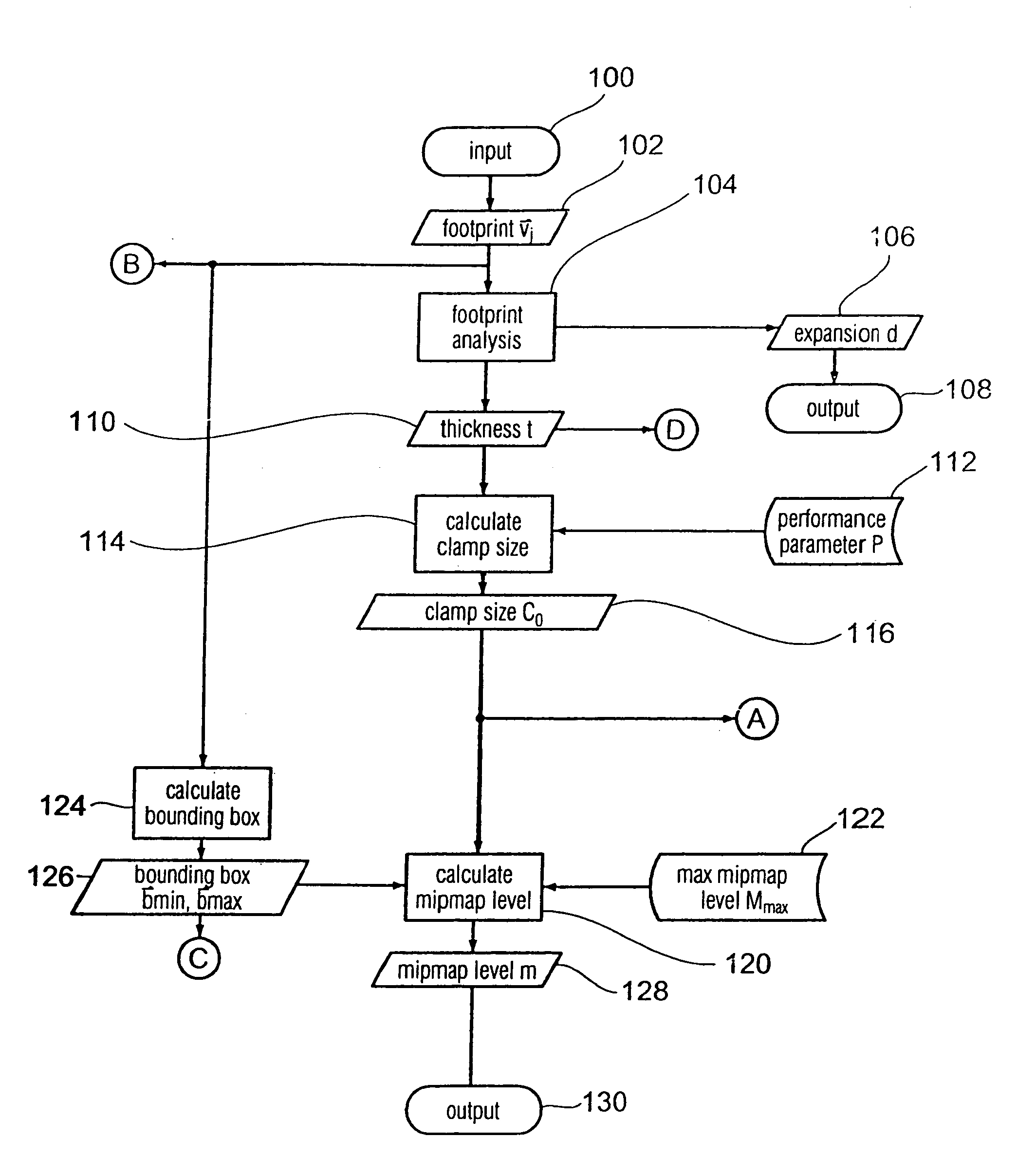
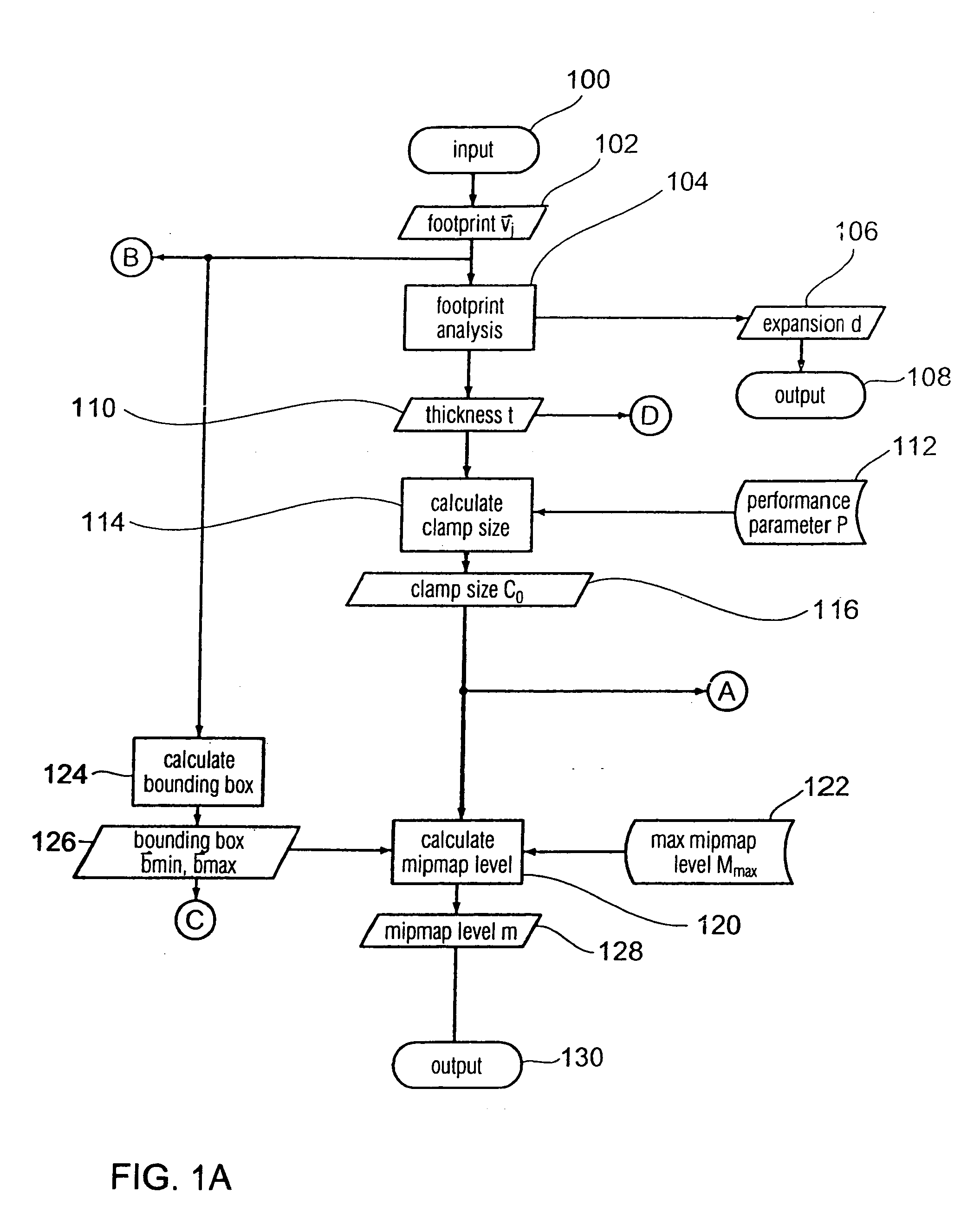
[0032] In accordance with the above-described preferred embodiment, a description will be given of essentially two approaches and / or techniques for restricting the number of texels used for representing a footprint (depending on the setting of the performance parameter P). If pre-filtered versions of a texture image having a
low resolution—the so-called mipmaps—are available, a suitable
mipmap level will be calculated on the basis of the thickness information. Hereby, the size of a square texel in the texel grid is then determined in an implicit manner. This calculation of the level is based on the actual spatial dimensions and / or the shape of the footprint. If no pre-filtered image map (
mipmap) having the level required is available, the area of the footprint is reduced by shrinking the boundaries (edges) of the footprint in a selective manner. This shrinking of the edges and / or reducing of the area is performed on the basis of the shape, the performance parameter P and a texel size of the next available image map (
mipmap) in the least favorable case, the next available image map is the original base map itself.
[0033] In accordance with a further preferred embodiment of the present invention, the incoming
quadrilateral footprint defined by its four vertices is initially analyzed with regard to its area and / or its shape and / or the spatial expansions of its edges. This analysis includes the following steps:

