Corrugated foam/film laminates for use as floor underlayment

Inactive Publication Date: 2005-07-21
SEALED AIR U S
View PDF22 Cites 48 Cited by
  • Summary
  • Abstract
  • Description
  • Claims
  • Application Information

AI Technical Summary

Benefits of technology

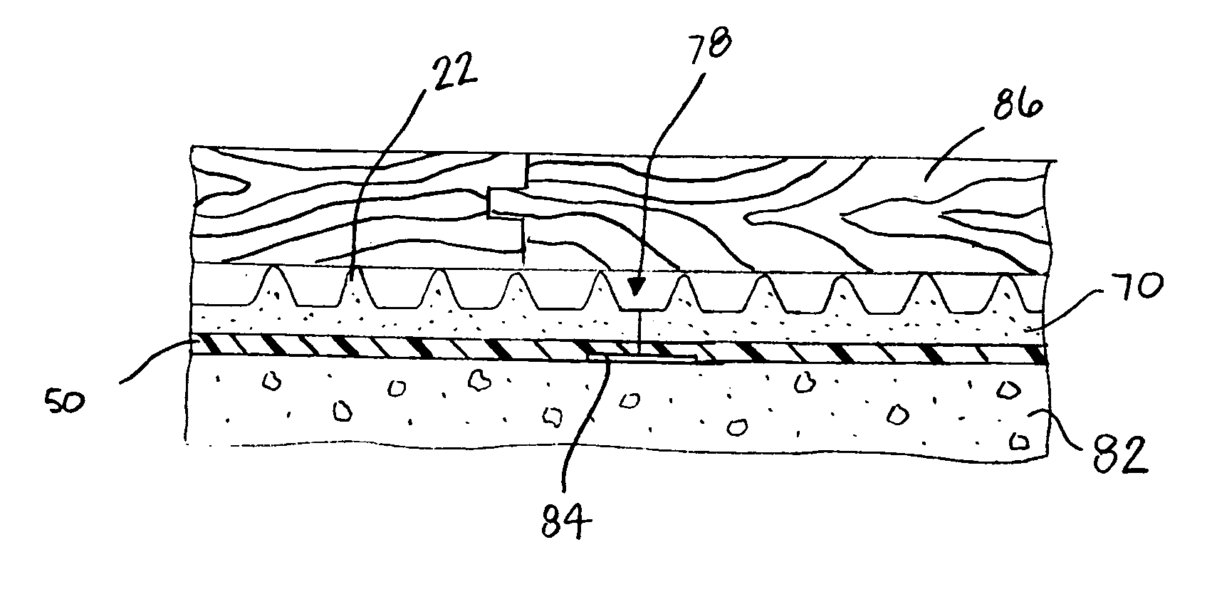
[0009] The foam web has a predetermined thickness between the first and second surfaces, and the ribs project from the first surface by a height dimension. Preferably, the height dimension is greater than the predetermined thickness of the web, and more preferably at least about twice as large as the predetermined thickness. The thickness of the foam web between the first and second surface may be between about 0.01 inches and about 1.50 inches. The overall thickness of the foam web, including the predetermined thickness and the height dimension, may be between about 0.02 inches and about 4 inches. Each of the ribs may be separated from an adjacent rib by any amount, but preferably by

Problems solved by technology

This may result in the development of mold, fungus and other growths, leading to odors and other health concerns.
In addition, because of the ten

Method used


Image

  • Corrugated foam/film laminates for use as floor underlayment
  • Corrugated foam/film laminates for use as floor underlayment
  • Corrugated foam/film laminates for use as floor underlayment

Examples


example 1

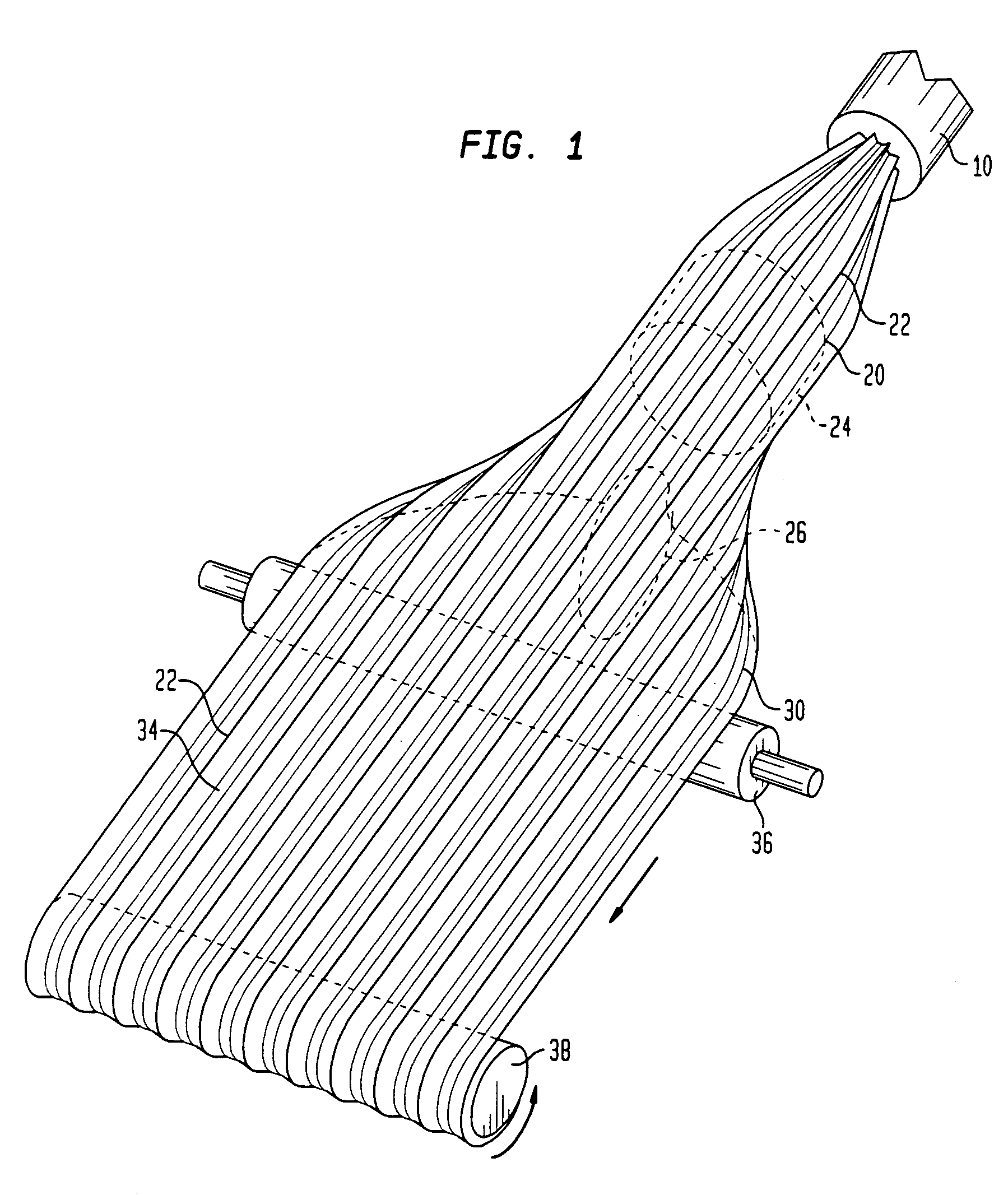
[0048] A low density polyethylene resin having a melt index of 2 g / 10 min and a density of 0.919 g / cm3 was combined in the feed zone of the primary extrusion chamber in a tandem extruder with 1.4 wt % of a nucleating agent masterbatch containing 50 wt % active talc and 50 wt % of the same low density polyethylene resin, and a 1.2 wt % of a permeation modifier mixture containing 66.7 wt % glycerol monostearate in 33.3 wt % monoethanolamide. The components were intricately fixed to form a homogenous polymer mixture. The mixture was then conveyed to the melt zone of the extruder and heated to a temperature of about 350° F. to form a molten mass. About 5.96 wt % (based on the weight of the resin) of an isobutane blowing agent was injected into the molten mass using a metering and pumping unit, and mixing continued until a homogenous blowing agent / polymer mixture was formed. This mixture was then conveyed to the secondary extrusion chamber in which it was cooled to a temperature of about...

example 2

[0050] A low density polyethylene resin having a melt index of 1.5 g / 10 min and a density of about 0.924 g / cm3 was combined in the feed zone of the primary extrusion chamber in a tandem extruder with 0.1 wt % of the same nucleating masterbatch used for Example 1, and 1.2 wt % of a permeation modifier mixture containing 66.7 wt % glycerol monostearate in 33.3 wt % monoethanolamide. The components were intricately mixed to form a homogenous polymer mixture. The mixture conveyed to the melt zone of the extruder and heated to a temperature of about 360° F. to form a molten mass. About 13.0 wt % (based on the weight of the resin) of a propane blowing agent was injected into the molten mass using a metering and pumping unit. Mixing of the ingredients continued until a homogenous blowing agent / polymer mixture was formed. This mixture was then conveyed to the secondary extrusion chamber of the extruder in which it was cooled to a temperature of about 234.5° F. Following stabilization, the m...


PUM


Abstract

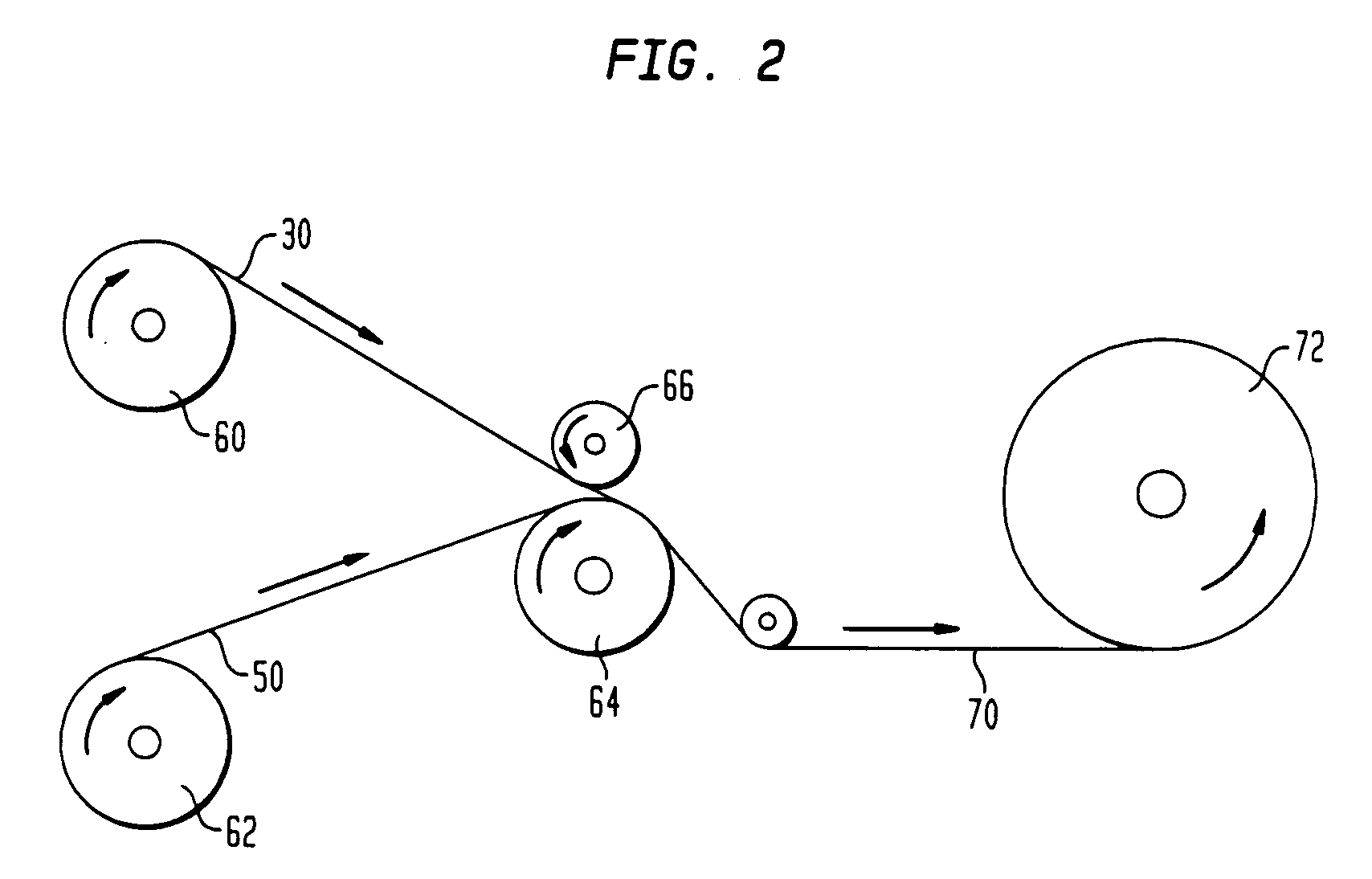
A laminate for use as a floor underlayment material includes a film disposed on at least one surface of an expanded foam web. The foam web includes a plurality of ribs projecting from one surface of the web in a length direction thereof so as to define a corrugated surface. The film is disposed on the surface of the foam web opposite the corrugated surface. The film is preferably formed from a high density polymer so as to enhance the moisture barrier properties of the laminate. When installed between a subfloor and finish flooring, the laminate defines channels which enable moisture emanating from the subfloor to be directed out from the flooring system.

Description

BACKGROUND OF THE INVENTION [0001] The present invention relates to expandable foams, and more particularly to expandable foams for use as a floor underlayment. Still more particularly, the present invention is directed to laminates of a film and an expandable foam useful as a floor underlayment. [0002] Flooring systems in residential and commercial buildings typically consist of wood or steel joists supporting a subfloor and finish flooring. In single-family and multi-family homes and small commercial buildings, the subfloor is often formed from wooden boards or panels laid over the joists. In apartment buildings, larger commercial buildings and other steel-frame buildings, the subfloor may be a steel deck, precast concrete slabs or panels, or poured concrete. [0003] The finish flooring is installed over the subfloor and provides a decorative, aesthetically pleasing floor surface. The finish flooring may be wood, such as wood planks, parquet flooring and wood-block flooring, or a r...

Claims


Application Information

Patent Timeline
IPC IPC(8): E04F15/18
CPCE04F15/18Y10T428/24504Y10T428/2457Y10T428/24496E04F15/182E04F15/185
Inventor RIVES, DAVIDRAMESH, NATARAJAN S.
Owner SEALED AIR U S
Why Eureka
Try Eureka