Vascular implant

a vascular implant and implant technology, applied in the field of medical devices, can solve the problems of high thrombosis, difficult delivery/retracement, and inability to treat stent grafts, and achieve the effect of increasing flexibility

Active Publication Date: 2020-08-11
NEUROGAMI MEDICAL INC
View PDF209 Cites 7 Cited by
  • Summary
  • Abstract
  • Description
  • Claims
  • Application Information

AI Technical Summary

Benefits of technology

[0027]In some embodiments, the filaments form a plurality of yarns, the plurality of yarns having spaces therebetween for blood inflow between the yarns. In some embodiments, the textile structure has a series of peaks and valleys along a surface of a wall to increase flexibility. In some embodiments the peaks and valleys are formed by crimping of the textile structure and extend in a longitudinal direction so transverse cross sections through the peaks have a greater height dimension than transverse sections through the valleys.
[0033]In some embodiments, a capillary effect is created within the vascular graft when the textile structure is exposed to blood such that blood is transported in a proximal direction through the implant wherein blood clots.
[0035]In some embodiments, a tube is positioned within coils of the inner element, the tube having engagement structure to engage a pusher of the delivery device, the pusher movable distally to advance the vascular graft from the delivery device. In some embodiments, the textile structure has a series of peaks and valleys along a surface of a wall to increase flexibility.

Problems solved by technology

Stent-grafts are not a treatment option for intracranial aneurysms due to the risk of cutting off blood flow to feeder vessels that may be vital for brain function.
Stent-grafts can also be stiff, hard to deliver / retract, and can be highly thrombogenic within the parent vessel, all of which are undesirable features for intracranial aneurysm treatment.
These materials pose a significant risk due to the difficulty of controlling dispersion and in retrieving them, if improperly or excessively delivered.
However, a balloon is difficult to retrieve, cannot be visualized unless filled with contrast, has the possibility of rupture, and does not conform to varying aneurysm shapes.
This device was difficult to introduce into tortuous vessel sites less than 3 mm in diameter.
This is generally because the coil was stiff or bulky and had a high coefficient of friction.
In addition, tight, mostly metal braids employing such designs result in stiff structures which are difficult to track via catheter or risk injury to the vasculature.
Also, metal braided structures may be rough to the touch if not covered or further processed.
Regardless of configuration, it is difficult to achieve high packing densities and rapid flow stagnation with these devices as they have open cell construction which allows at least some blood flow through the wall, may not compress adequately, and / or may have limited bend radii.
If an aneurysm sac is not sufficiently packed to stop or slow blood flow, any flow through the neck of the aneurysm may prevent stasis or cause coil compaction, leading to recanalization of the aneurysm.
Conversely, tight packing of metal coils in large or giant aneurysms may cause increased mass effect (compression of nearby tissue and stretching of aneurysm sac) on adjacent brain parenchyma and cranial nerves.
Coil prolapse or migration into parent vessels is another possible issue with non-expanding devices, especially in wide neck aneurysms.
A major problem for these designs is sizing.
Undersized devices lead to insufficient packing as described above, whereas oversizing risks rupturing the aneurysm or blockage of parent vessel.
Regardless of design, neck bridges pose several problems when treating intracranial aneurysms.
The first major challenge is deployment of these devices, which requires the bridge to be maneuvered and often re-positioned over the aneurysm neck to assure complete coverage.
Secondly, if recanalization occurs, any subsequent retreatment of the aneurysm will be hampered due to access being restricted by the neck bridge or one of its components.
However, complications such as recanalization, delayed stent thrombosis, delayed aneurysm rupture, and stent migration have also been observed.
Achieving all these objectives without favoring / emphasizing one at the expense of another presents a difficult challenge.
Further compounding the challenge is the fact that since the device is designed for minimally invasive insertion, it needs to be easy to deliver and deploy at the intracranial site as well as manufacturable in a small enough size for use in cerebral vasculature.
To date, no device effectively achieves all these objectives, with current devices at best achieving one objective at the expense of the others.

Method used


Image

  • Vascular implant
  • Vascular implant
  • Vascular implant

Examples


Embodiment Construction

[0112]The following embodiments are described in sufficient detail to enable those skilled in the art to practice the invention, and it is understood that structural changes may be made without departing from the scope of the present invention. Therefore, the following detailed description is not to be taken in a limiting sense. Where possible, the same reference numbers are used throughout the drawings to refer to the same or like components or features.

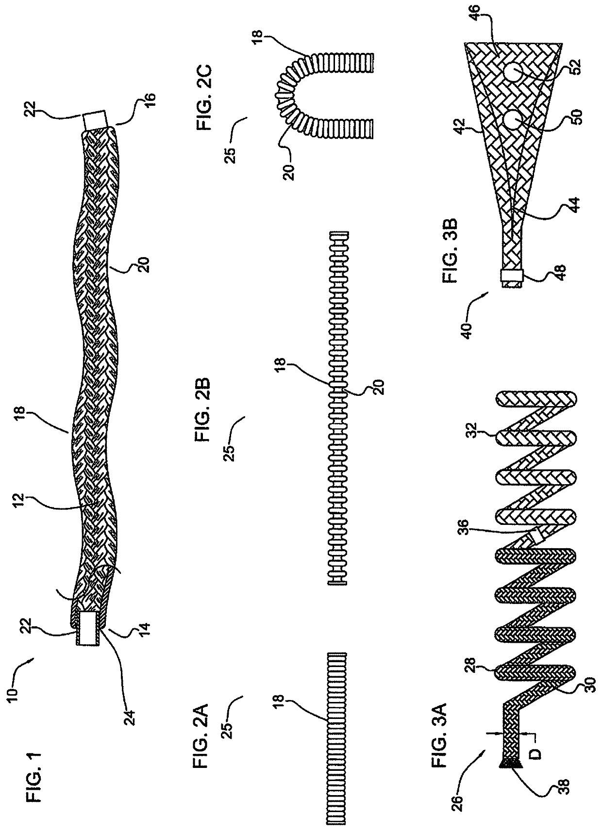
[0113]FIG. 1 illustrates a partial cut away side view of an intra-aneurysmal micrograft for insertion into an intracranial aneurysm in accordance with one embodiment of the present invention. The micrograft of this embodiment, designated generally by reference number 10, includes a biocompatible non-self-expandable absorbent braided polymeric textile tubular body 12 that has been crimped to reduce stiffness and increase wall thickness and fabric density. The micrograft 10 has sufficient stiffness as well as sufficient flexibility to...


PUM

PropertyMeasurementUnit
lengthaaaaaaaaaa
lengthaaaaaaaaaa
diameteraaaaaaaaaa

Abstract

A vascular graft configured for occluding a vasculature of a patient including a biocompatible polymeric textile structure formed of a plurality of filaments spaced to enable blood flow through spaces between the filaments. The textile structure forms a tubular body having a first longitudinally extending opening. An inner element has a proximal end and a distal end, the inner element composed of an open pitched metal coil having a second longitudinally extending opening and is positioned within the longitudinally extending opening of the textile structure.

Description

[0001]This application claims priority from provisional application Ser. No. 62 / 457,871, filed Feb. 11, 2017, and is a continuation in part of application Ser. No. 14 / 997,094, filed Jan. 15, 2016 which claims priority from provisional application 62 / 106,648, filed Jan. 20, 2015. The entire contents of each of these applications are incorporated herein by reference.BACKGROUNDTechnical Field[0002]This application relates to medical devices, and more particularly, to vascular implants for occluding vasculature and methods of manufacturing the vascular implants.Background of Related Art[0003]An aneurysm is a localized, blood filled balloon-like bulge that can occur in the wall of any blood vessel, as well as within the heart. There are various treatments for aneurysms. One endovascular treatment option for aneurysms is complete reconstruction of the damaged vessel using a vascular prosthesis or stent-graft. A stent-graft is an implantable tubular structure composed of two parts, a stent...

Claims


Application Information

Patent Timeline
Patent Type & Authority Patents(United States)
IPC IPC(8): A61B17/12A61F2/07A61F2/90A61F2/91A61F2/06A61F2/01A61F2/94A61F2/82A61B17/00
CPCA61F2/90A61F2/91A61B17/12118A61B17/12113A61F2/07A61B17/1215A61B2017/12054A61F2002/823A61B2017/00526A61F2/94A61F2210/0004A61F2230/0091A61F2002/068A61F2002/018
Inventor HEBERT, STEPHEN J.BOJANOWSKI, BARTOSZ
Owner NEUROGAMI MEDICAL INC
Why Eureka
Try Eureka