Surface mounted oven controlled type crystal oscillator

Inactive Publication Date: 2011-08-11
NIHON DEMPA KOGYO CO LTD
View PDF3 Cites 19 Cited by
  • Summary
  • Abstract
  • Description
  • Claims
  • Application Information

AI Technical Summary

Benefits of technology

[0020]With such a construction, the ceramic first substrate on which circuit elements including a crystal device for surface mounting are installed, faces the glass epoxy resin second substrate having mounting terminals on the outside bottom surface, and is electrically and mechanically connected thereto. Furthermore, the oven controlled oscillator is constructed with the front end side head section of the crystal device disposed inside the open surface of the second substrate. Accordingly, in comparison to the case of the conventional example in which the second substrate surface-bonded to the first substrate is held in place upon the surface mounting base by metal pins, the height dimension of the oven controlled oscillator can be greatly reduced. Moreover, because the crystal device is disposed within the open surface of the opening section of the second substrate, by means of the external (mounting) terminals provided on the outside bottom surface of the second substrate, a surface mountable oven controlled oscillator is obtained.
[0021]Furthermore, the first substrate on which the crystal device and heating resistor are provided is composed of ceramic, and the crystal device enters and is located inside the open surface of the opening section of the second substrate made of glass epoxy resin. Accordingly, the oven-controlled oscillator, when surface-mounted with other electronic components onto a set substrate (typically made of glass epoxy resin), is surrounded such that the outside bottom surface of the crystal device faces the first substrate (ceramic) which has the resistor as a heat source and offers good thermal conductivity, the four outside surfaces thereof face the inside of the opening section of the second substrate (glass epoxy resin) which has a shielding effect due to poor thermal conductivity, and the front end side faces the set substrate. Thus, the opening section forms a so-called pseudo-enclosed space.
[0022]Accordingly, the heat produced by the heating resistor is retained inside the opening section 12 and cannot easily escape, enabling the efficient utilization of heat energy and simplifying temperature control. In this case, because the heating resistor need on

Problems solved by technology

However, in the conventional oven controlled oscillator of the above configuration, as shown in FIG. 11B, because the second substrate 11b joined to the first su

Method used


Image

  • Surface mounted oven controlled type crystal oscillator
  • Surface mounted oven controlled type crystal oscillator
  • Surface mounted oven controlled type crystal oscillator

Examples


first embodiment

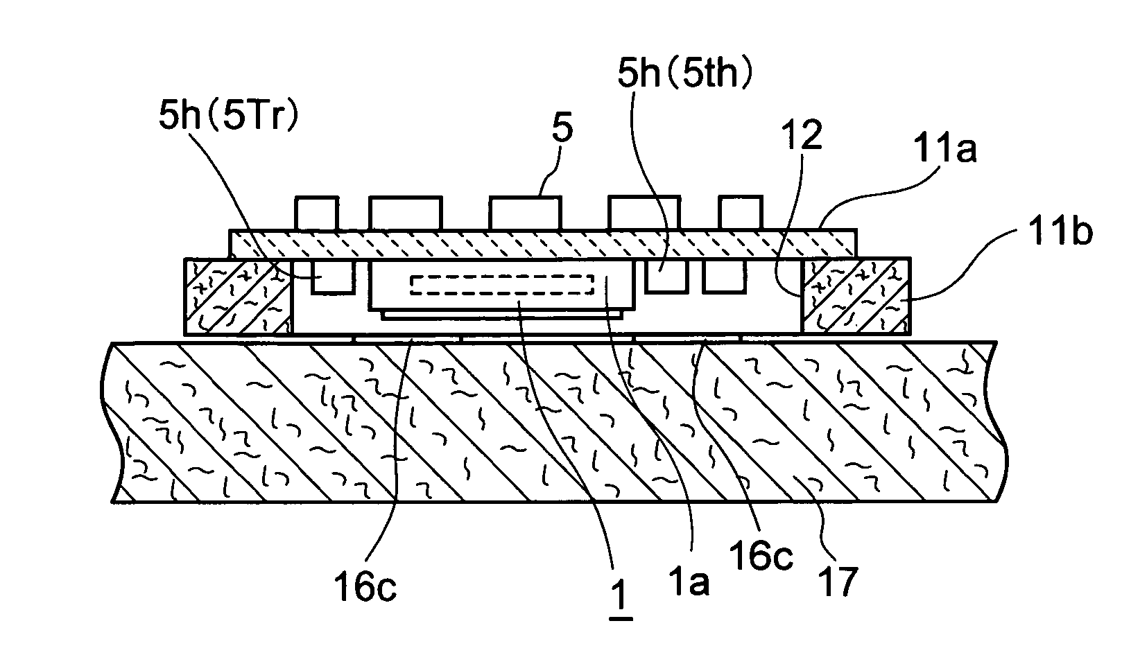
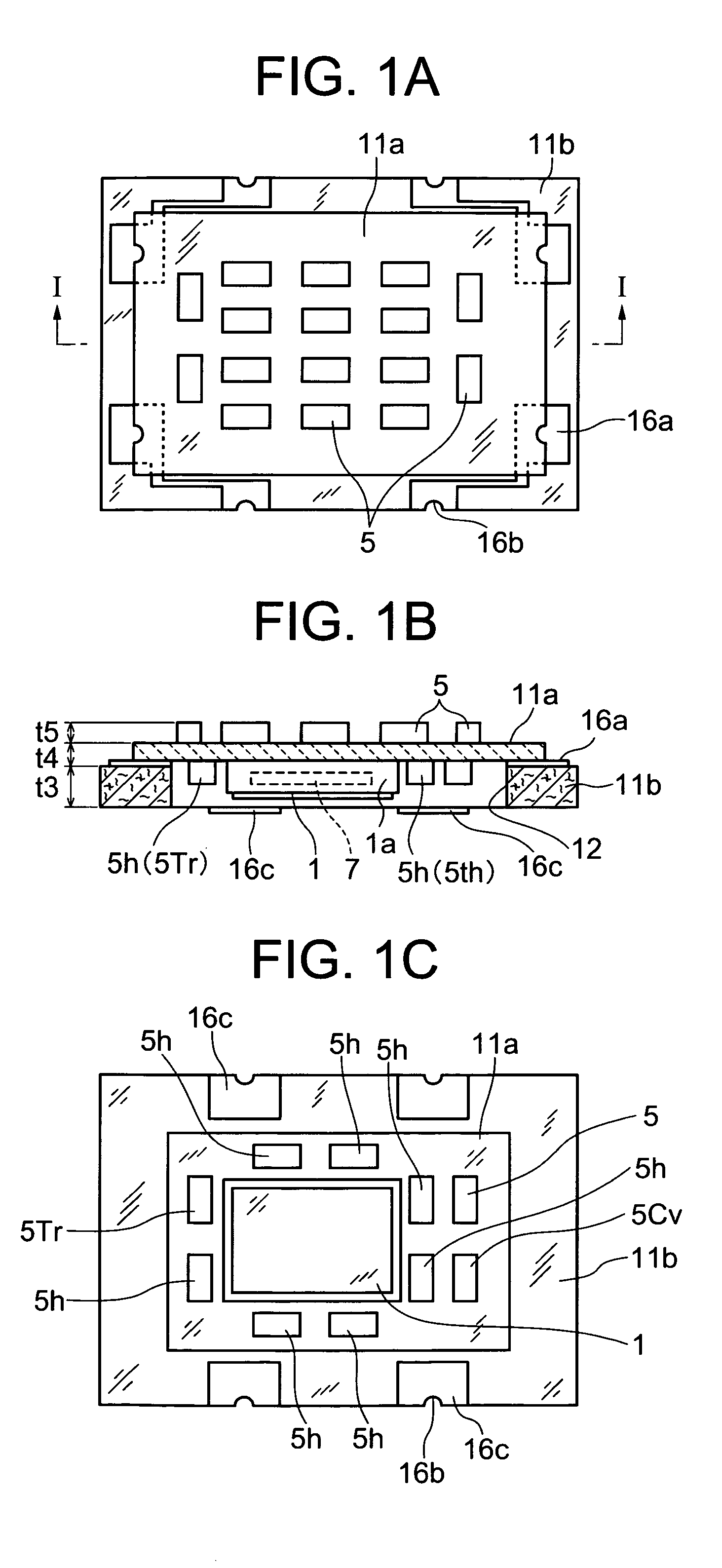
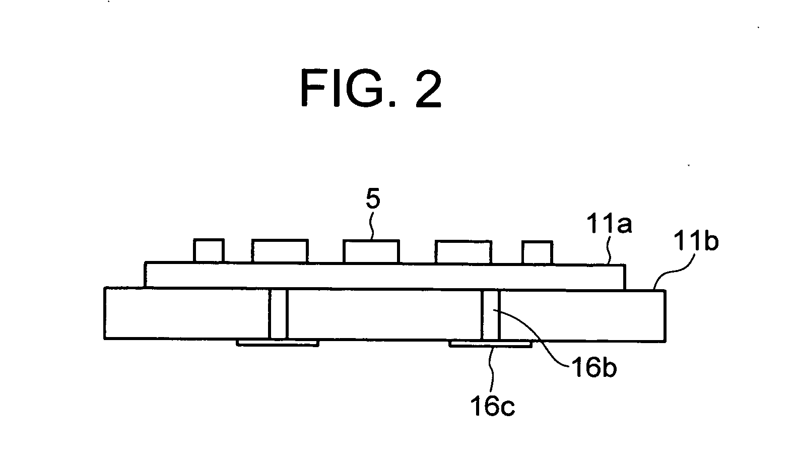
[0045]As follows is a description of a first embodiment of an oven controlled oscillator of the present invention with reference to FIG. 1 (plan view (FIG. 1A), cross-sectional view (FIG. 1B), and bottom view (FIG. 1C) of oven controlled oscillator), FIG. 2 (front view of same), FIG. 3 (first substrate), and FIG. 4 (second substrate).

[0046]The oven controlled oscillator of the present invention, as shown in FIG. 1B, comprises a flat first substrate 11a made of ceramic, and a second substrate 11b which is made of a glass epoxy resin and has an opening section 12 at its center. The first substrate 11a and the second substrate 11b are both a quadrangle shape in plan view, in this case rectangular, the second substrate 11b has larger external dimensions in plan view than the first substrate, and the substrates face each other in alignment in the width direction and the length direction. Furthermore, on one principal surface of the first substrate 11a serving as the bottom surface side, ...

second embodiment

[0059]In the second embodiment (see FIG. 7A, FIG. 7B) of the present invention, the heating resistor, instead of the chip element (heating resistor 5h) of the first embodiment, is a film resistor (heat resistor film) 5h′, and the thermistor 5th serving as the thermal sensor is also a film resistor (thermistor film 5th′). Here, one principal surface (bottom surface side) of the first substrate 11a is formed so as to face the central region of the outside bottom surface of the crystal resonator 1. Furthermore, the thermistor film 5th′ serving as the thermal sensor faces the outside bottom surface of the crystal resonator 1, and is formed adjacent to the heat resistor film 5h′. Moreover, at the outer periphery of the crystal resonator 1, the power transistor 5tr acting as a heat source, and the highly temperature-dependent voltage variable capacitative element 5Cv and the like are disposed. Reference numeral 19 in FIG. 7A includes the mounting terminals of the crystal resonator 1, and ...

third embodiment

[0062]In a third embodiment (see FIG. 9A, FIG. 9B) of the present invention, an IC chip 21 which integrates most of the circuit elements 5 for oscillation and temperature control is disposed on a principal surface of the first substrate 11a by, for example, flip-chip bonding. The IC chip 21 is covered by a resin (not shown). Here, for example, integration is performed with the exception of the power transistor 5tr and the heat resistor film 5h′, the thermistor film 5th′, large capacitors and the like which are difficult to integrate, and, for example, circuit elements 5 which require their oscillation frequency to be adjustable. Furthermore, the entire surface of the other principal surface (top surface) opposite from the one principal surface of the first substrate 11a is exposed.

[0063]Thus, by eliminating the circuit elements 5 from the other principal surface of the crystal resonator 1, the height dimension of the oven controlled oscillator can be further reduced. In this example...


PUM


Abstract

The invention relates to an oven controlled crystal oscillator for surface mounting with reduced height (low profile). The oven controlled crystal oscillator for surface mounting comprises: a flat first substrate made of ceramic and on which are installed a crystal device and a heat resistor; and a second substrate made of a glass epoxy resin which is quadrangular in plan view and which faces the first substrate and has a larger external shape in plan view than the first substrate. The second substrate has an opening into whose center the crystal device is inserted, and has terminal sections on four locations corresponding to the surface outer periphery of the first substrate and the peripheral surfaces of the opening in the second substrate, and the terminal sections of the first substrate and second substrate are connected by solder. A front end side head section of the crystal device inserted into the opening section of the second substrate is positioned inside the open surface of the opening section, and from terminal sections provided at four locations on the second substrate, conductive paths extend via the outside surface of the second substrate to external terminals formed on the outside bottom surface of the second substrate.

Description

BACKGROUND OF THE INVENTION[0001]1. Technical Field[0002]The present invention relates to an oven controlled type crystal oscillator for surface mounting (hereafter “oven controlled oscillator”), in particular to an oven controlled oscillator which facilitates a low profile.[0003]2. Background Art[0004]Oven controlled oscillators, being able to impart a constant operating temperature to crystal resonators in particular, can eliminate frequency changes that result from frequency temperature characteristics, thereby stabilizing the oscillation frequency. Thus, stability of the oscillation frequency is obtained in the order of parts per billion, for example, for such applications as a frequency source in a base station. In recent years, although such highly stable oven controlled crystal oscillators have been reduced in size and adapted for surface mounting, demand exists for further reductions in height.[0005]3. Prior Art[0006]FIG. 11A, 11B, and FIG. 12 illustrate a conventional examp...

Claims


Application Information

Patent Timeline
IPC IPC(8): H03B1/00H03L1/00
CPCH03H9/05H03B5/32H03H9/0552H03H9/02102H03H9/0542H03H9/1021H03H9/105
Inventor KASAHARA, KENJI
Owner NIHON DEMPA KOGYO CO LTD
Why Eureka
Try Eureka