
Polypropylene foam and foam core structure

a polypropylene foam and core structure technology, applied in the field of polypropylene foam and foam core structure, can solve the problems of difficult to difficult to actually manufacture foams from polypropylene, and inconsistent cell formation of foams, so as to reduce the diffusion rate of physical blowing gases and reduce the diffusion

Inactive Publication Date: 2005-07-21
ARMACELL ENTERPRISE GMBH & CO KG
View PDF34 Cites 67 Cited by
  • Summary
  • Abstract
  • Description
  • Claims
  • Application Information

AI Technical Summary

Benefits of technology

[0079] One or more external surfaces of an extruded foam are coated by co-extruding a skin of polymer on the surface to reduce the diffusion the foaming gases out from the cells of the solidifying polymer foam. The skin or skins is / are applied inside of the co-extrusion die while the polymer gas mixture is at high pressure and the gas is dissolved in the polymer. The sealing effect of this can be accomplished by simply coating one side of the extruded foam (the AB form) The effect is much more dramatic if both surfaces of the extruded foam are co-extruded with skins of polymer (the ABA form). The skins can be solid or can themselves be foamed. It is preferred that the density reduction of the skin layers will be less than the density reduction of the main foam layer. The skins can be foamed by chemical or physical foaming agent or by combination of chemical and physical foaming agents. Even more effective, is a process involving an annular die and, preferably, a cylindrical cooling mandrel. The cylindrical co-extrusion seals even the edges of the laminate. By extruding and drawing the cylinder of foam onto a cooled cylindrical mandrel, which expands the diameter of the cylinder, the maximum physical properties of the structure can be achieved. This is because the foam structure is stretched in longitudinal and lateral directions. Preferable, the foaming polymer has and exhibits “inherent melt strength” and “strain hardening” so that the foam cells are more consistent in size and shape. The preferred polymers are polypropylene or polystyrene.
[0083] The essence of this invention is to develop techniques to reduce the diffusion rates of the physical blowing gases out of the molten extruded material so that the gases remain in the foamed material while the polymer is solidifying and so that the gases are captured in the solidifying polymer.
[0084] The key element of this invention is the idea that one or more external surfaces of the extruded foam are coated by co-extruding a layer of polymer on the surface to reduce the diffusion the foaming gases out for the cells of the solidifying polymer foam. The layer or layers are applied inside of the die while the polymer gas mixture is at high pressure and the gas is dissolved in the polymer. The sealing effect of this can be accomplished by simply coating one side of the extruded foam (the AB form). The effect is much more dramatic if both surfaces of the extruded foam are co-extruded with layers of polymer (the ABA form).
[0086] A process involving an annular die and cylindrical cooling mandrel is preferred. By extruding and drawing the cylinder of foam onto a cooled cylindrical mandrel, which expands the diameter of the cylinder, the maximum physical properties of the structure can be achieved. This is because the foam structure is stretched in longitudinal and lateral directions.

Problems solved by technology

However it is very difficult to actually manufacture foams from polypropylene.
Attempts to extrude polypropylene foams using chemical blowing agents have resulted in foams that have very inconsistent cell formation.
Attempts at using physical blowing agents have generally been unsuccessful because the high pressure and rapid diffusion of physical blowing agents such as carbon dioxide or nitrogen at the high processing temperature of polypropylene.
Foaming of polypropylene is further complicated by the low inherent melt strength as exhibited by lack of “strain hardening”.
These factors result in inconsistent and collapsed or open cells.
The cost of these modified polymers is significantly increased over standard PP.
However low solubility and high pressure at processing temperature complicate their use.

Method used


Image

  • Polypropylene foam and foam core structure
  • Polypropylene foam and foam core structure
  • Polypropylene foam and foam core structure

Examples


Embodiment Construction

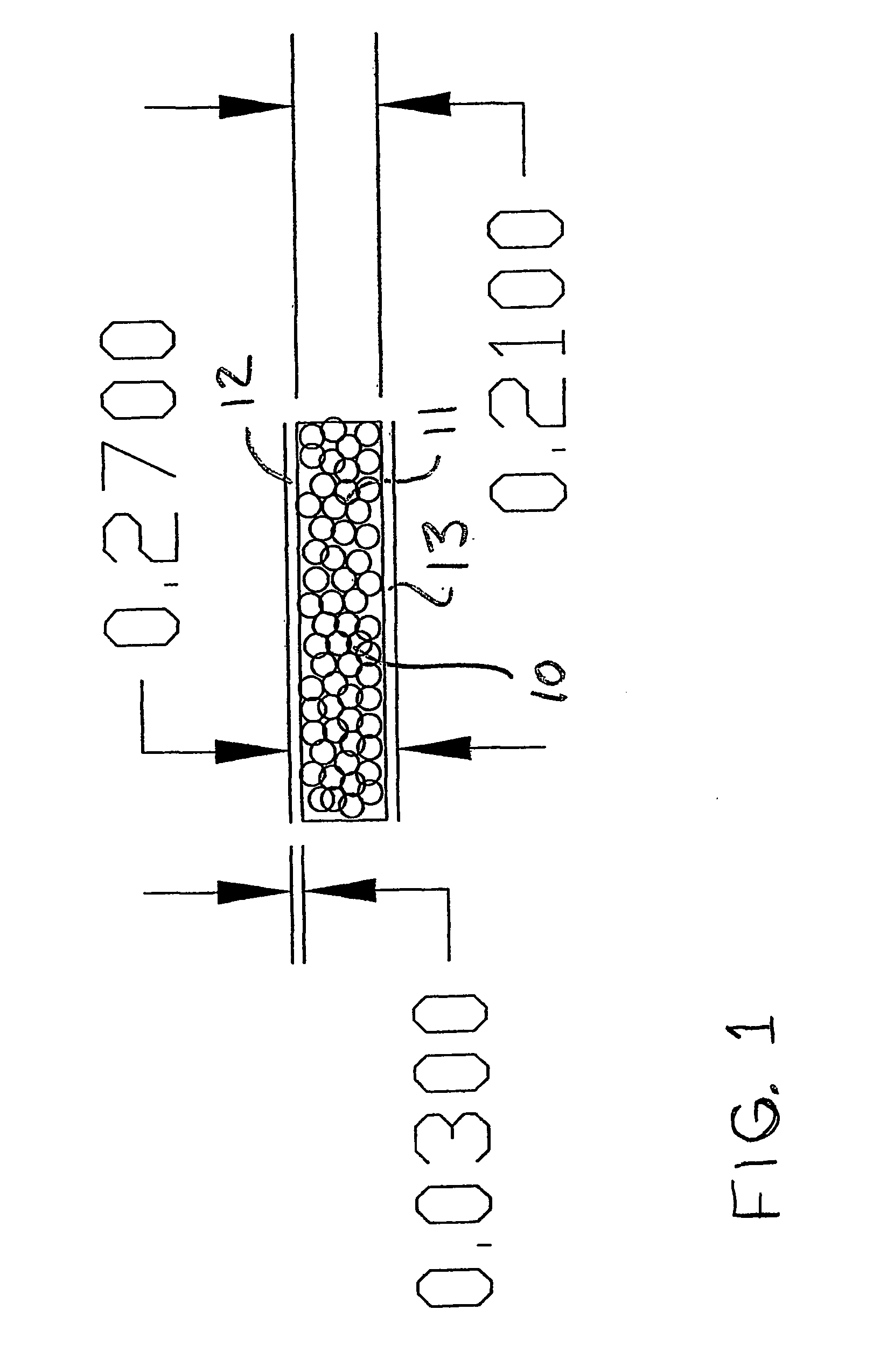
[0096] The principles of the invention can be best understood by reference to the drawing. FIG. 1. is a front elevation of a skin-core-skin (ABA) laminate embodying the principles of the present invention. The laminate, generally designated by the numeral 10, is formed of a foamed core 11, and at least one 12 one side of the core 11. This is referred to as an AB construction. In the preferred embodiment, the laminate would also have a second skin 13 coating the opposite side of the core from the first skin 12.

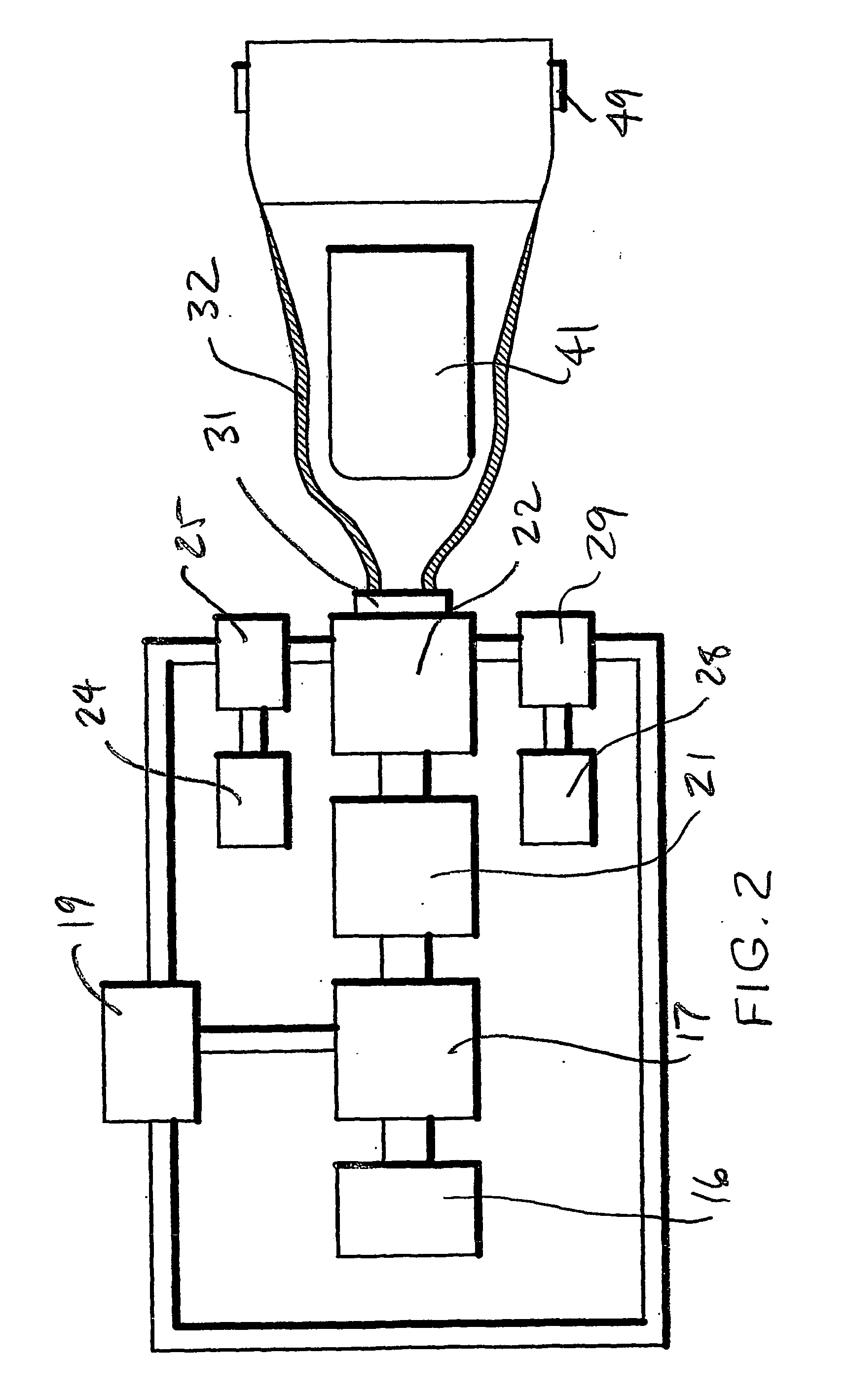
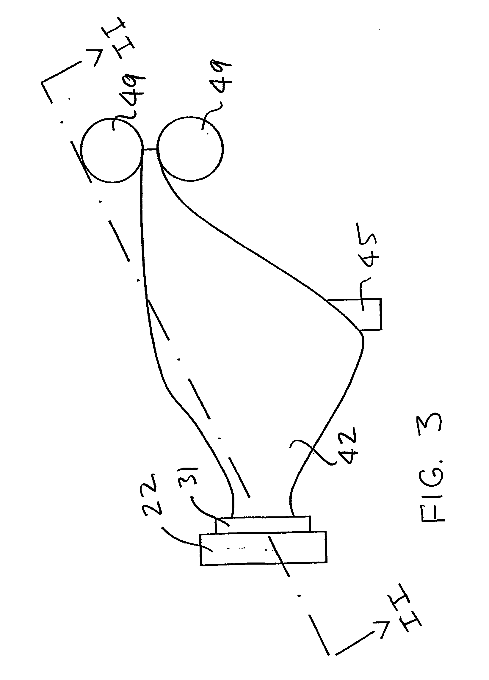
[0097]FIG. 2 is a plan view of a production line for co-extruding a cylinder, expanding the cylinder, slitting the cylinder, flattening the resulting product and drawing the product through rollers, with the cylinder being shown as a sectional view along line II-II of FIG. 3, all embodying the principles of the present invention. The core polymer 15 is fed from a core polymer reservoir 16 to a mixer 17 where it is combined, under high-pressure, with physical blowing gas 18 fro...


PUM

PropertyMeasurementUnit
Melt Flow rateaaaaaaaaaa
melt flow rateaaaaaaaaaa
foamableaaaaaaaaaa

Abstract

One or more external surfaces of an extruded foam are coated by co-extruding a skin of polymer on the surface to reduce the diffusion the foaming gases out of the cells of the solidifying polymer foam. The sealing effect can involve coating one side of the extruded foam (AB foam) or both sides (ABA form). The skins can be solid or foamed. Alternatively, a cylinder is formed from an annular die and, preferably, a cylindrical cooling mandrel. By extruding and drawing the cylinder of foam onto a cooled cylindrical mandrel, which expands the diameter of the cylinder, the optimum physical properties of the structure can be achieved. This is because the foam structure is stretched in longitudinal and lateral directions. Preferable, the foaming polymer has “inherent melt strength” and “strain hardening” so that the foam cells are more consistent in size and shape. The preferred polymers are polypropylene or polystyrene.

Description

CROSS-REFERENCE TO RELATED APPLICATIONS [0001] This application claims the benefit under 35 U.S.C. §119(e) of prior U.S. Provisional Application No. 60 / 362,728, filed Mar. 7, 2002 and prior U.S. Provisional Application No. 60 / 362,819 filed Mar. 8, 2002; both of which are hereby incorporated by reference.STATEMENT REGARDING FEDERALLY SPONSORED RESEARCH OR DEVELOPMENT [0002] This invention has been created without the sponsorship or funding of any federally sponsored research or development program. FIELD OF THE INVENTION [0003] This invention involves a co-extrusion method for forming a foam core polymer laminate and the laminate. BACKGROUND OF THE INVENTION [0004] This invention identifies the product and process to produce a polypropylene foam and / or a multi-layered composite structure utilizing a foamed polypropylene core with additional layers of foamed or solid polypropylene or other thermoplastic or thermoset materials. The structure can be in the form of a flat sheet, tubular ...

Claims


Application Information

Patent Timeline
Patent Type & Authority Applications(United States)
IPC IPC(8): B29C44/22B32B5/18B32B27/32C08J9/00C08J9/12C08J9/36
CPCB29C44/22B32B5/18C08J9/0061C08J9/122C08J2423/00C08J2201/03C08J2323/10C08J2325/06C08J9/365C08J9/00C08J9/14B32B2439/70B32B2439/80B32B5/32B32B5/20B32B2307/306B32B2307/21B32B1/08B32B2310/0454B32B37/153B32B27/065B32B2605/08B32B27/18
Inventor BAMBARA, JOHN DBECKWITH, ROBERT W.HOOPER, ROBERTHURLEY, ROBERT
Owner ARMACELL ENTERPRISE GMBH & CO KG
Learn More